Carlisle Ransburg 19372 Service Manual Download Page 42

PARTS IDENTIFICATION

EN

AH-13-01-R8  (09/2022)

42 / 55

www.carlisleft.com

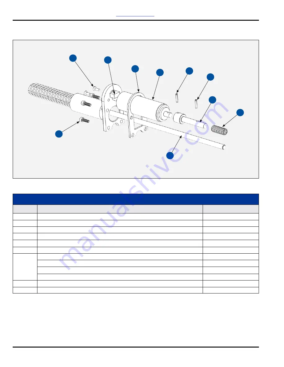
Figure 27: Cable /Motor Parts List

Item #

CABLE / MOTOR PARTS LIST


(Figure 27)

Description

Part #

1  

Spring Pin  

4359-01

2  

Spring 

8491-00

3  

Adaptor, Drive 

75757-00

4  

Assembly, Electric Motor No. 2 

3639-00

5  

Gasket, No. 2 Handgun 

3968-00

6  

SHCS #8 Screw (4) Required 

8301-16C

7  

Assembly, Cable No. 2 Electric Motor (With Motor & Switch/Without)


  7.6 m (25’) length 

19371-25 / 19370-25


  11 m (36’) length 

19371-36 / 19370-36


  15.2 m (50’) length 

19371-50 / 19370-50

8  

Switch 

4125-00

9  

Screw, Flat HD. #10 

9157-24F

5

8

1

9

4

1

7

2

3

6

Return To Contents

Summary of Contents for Ransburg 19372

Page 1: ...EN SERVICE MANUAL AH 13 01 R8 09 2022 1 55 www carlisleft com No 2 Process Handgun Electric Motor Version Model 19372...

Page 2: ...AH 13 01 R8 09 2022 2 55 www carlisleft com NOTE ThismanualhasbeenchangedfromrevisionAH 13 01 R7torevision AH 13 01 R8 Reasons for this change are noted under Manual Change Summary inside the back cov...

Page 3: ...ed Tube Bell and Brush 15 Accessory Installation 16 No 2 Handgun Brush Positioning and Wear 17 Paint 18 OPERATION 19 23 Procedures 19 Operations Near Computers or Other Electronic Devices 20 Shutdown...

Page 4: ...edle Valve Assembly Parts List 44 Barrel Parts List 45 8340 XX Fluid Hose Parts and Assemblies 46 Feed Tube Parts 47 Brush Assembly Parts 47 Fluid Filter Parts 48 Bell Spare Parts and Assemblies 49 90...

Page 5: ...ationdrawingsandassociatedequipment manuals to reconcile such differences The user MUST read and be familiar with the Safety Section in this manual and the safety literature therein identified This eq...

Page 6: ...d off prior to cleaning flushing or maintenance Spray booth ventilation must be kept at the rates required by NFPA 33 EN 16985 country and local codes In addition ventilation must be maintained during...

Page 7: ...on Hazard Electrostatic arcing must be prevented Safe sparking distance must be maintained between the parts being coated and the applicator A distance of 1 inch for every 10KV of output voltage is re...

Page 8: ...e used to assure adequate ground contact Operators must not be wearing or carrying any ungrounded metal objects When using an electrostatic handgun operators must assure contact with the handle of the...

Page 9: ...approved for use in hazardous locations the power supply control cabinet and all other electrical equipment must be located outside Class I or II Division 1 and 2 hazardous areas in accordance with N...

Page 10: ...ic spray products on the market The No 2 Electric Process Handgun applies a DC negative charge to the coating materials at the point of atomization The electrostatic charge allows a more efficient uni...

Page 11: ...CI From Brush 115 microamperes maximum Fluid Input Pressure 3 45 bar 50 psig maximum Air Input Pressure 6 90 bar 100 psig maximum Fluid Delivery Rate Maximum 2 3 4 Bell Size 75 cc minute 2 5 fl oz min...

Page 12: ...Description 8 KV SETPOINT ADJUST BUTTONS 9 AIR FLOW SWITCH CONNECTIONS 10 HIGH VOLTAGE CABLE CONNECTOR 11 FUSES 12 GROUNDING LUG 13 AC INLET RECEPTACLE 14 DOOR KEY LOCK Item Description Item Descripti...

Page 13: ...wer supply ground wire to ground target objects The targets objects must have separate true earth ground for best efficiency NEVER wrap the applicator associated valves and tubing and supporting hardw...

Page 14: ...tube as shown in Figure 3 below FLUID HOSE Refer to Figure 4 Install the fluid filter to the applicator then to the fluid delivery hose Attach one end of the fluid hose to the adapter This adapter has...

Page 15: ...o available as optional lengths FLUID FITTING INSTALLATION PROCEDURE 1 Lubricate all fittings with dielectric grease 2 Screw ferrule item 3 counterclockwise onto hose item 4 until it bottoms then back...

Page 16: ...Motor Shaft Shaft Locating Flat Bell Set Screw Bell The Bell Cleaning Can provides a convenient and portable method of removing excess materials from the bell cup at the conclusion of spray ACCESSORY...

Page 17: ...rush arm should lightly contact the black bell coating not the wire The wire should never contact the coating The tip of the brush should not extend past the edge of the bell cup or into the radius at...

Page 18: ...burg distributor See Paint and Solvent Specifications in the Appendix section of this service manual Most paint suppliers may be of assistance in pre adjusting the paint for proper electrostatic spray...

Page 19: ...he 9060 power ON OFF switch on the front panel to the ON position as shown in Figure 12 The unit will power up but high voltage will not be on at this point because the voltage is interlocked to the e...

Page 20: ...ll size or improper electrical resistance of the coating material Adjust parameters according to atomization quality and results For an accurate measurement of paint delivery with any paint being used...

Page 21: ...olvent Specifica tions in the Appendix section of this manual BEFORE attempting any cleaning or color change procedures the high voltage and the AC power to the power supply MUST be turned OFF The bel...

Page 22: ...fety containers 4 Reposition the feed tube to the five o clock position and trigger the gun into a grounded container until there is no evidence of paint in the stream 5 Release the trigger and remove...

Page 23: ...All paints and solvents must be purged from the applicator prior to performing these tests 2 Activate the applicator by turning the switch to the ON positiontospintheelectricmotorandinitiatehighvoltag...

Page 24: ...ent should be avoided when working with the No 2 Handgun It not only effects the bell performance but also has a very low flash point 20o C 4 F No 2 Handgun bells should NOT be cleaned in it and the u...

Page 25: ...MPONENTS IN PLASTIC WILL VOID WARRANTY TEST PROCEDURES Fluid Testing Needle Locknut Adjustment When the paint does not shut off after the trigger has been released adjust the knurled nuts in front of...

Page 26: ...High voltage components such as cable and high voltage resistor are not field serviceable For repair or replacement of such items contact your Ransburg distributor Tools Required 14 5 mm 9 16 inch Ope...

Page 27: ...element from the rear housing 3 If a new paint filter is to be installed clean the front housing and rear housing using the appropriate solvent 4 If the same paint filter is to used wash the paint fi...

Page 28: ...Figure 17 Description 4 Socket Head Screws 2 Slotted Head Screws High Voltage Cable Assembly Switch Gasket Electric Motor Assembly 4 Inspect gasket for any damage Replace if required 5 Check the appli...

Page 29: ...the 4 socket head cap screws and lock washers from the underside of the handle assembly with a 9 64 inch hex key wrench Refer to Figure 18 Figure 18 Handle Assembly Removal Item Description 1 2 3 4 5...

Page 30: ...bly Also make sure that the trigger latch spring is aligned with the top edge of the handle 3 With the handle tang supported use a 3 mm 1 8 punch and a small hammer to gently drive the roll pin throug...

Page 31: ...the Maintenance section 2 Remove the spring retainer with a 1 4 inch open end wrench and slide the needle assembly out of the handle It is not necessary to remove the two lock nuts and the thrust was...

Page 32: ...ntil it bottoms 9 To install the needle assembly refer to steps 3 through 6 of Needle Assembly Replacement in the Maintenance section Needle Packing Replacement 1 Complete steps 1 and 2 under Needle A...

Page 33: ...nconductive solventanddrythoroughly Referto EffectsofSolvents in the Maintenance section Inspect the ID of each end of the resistor tube for any signs of high voltage tracking or arcing Item Descripti...

Page 34: ...w O ring Item 2 onto resistor seal Item 3 Apply a thin coating of petroleum jelly to the O ring and place it against the resistor hole side towards the resistor Push the resistor seal into the tube un...

Page 35: ...he motor 5 Remove the remaining two O rings Items 4 and 9 from the drive shaft 6 Discard the ceramic seal Item 5 PTFE seal Item 8 O rings Items 4 6 and 9 Examine the drive shaft and replace if damaged...

Page 36: ...or Dielectricgreaseshouldonlybeusedasafiller displacement of air to suppress high voltage corona Dielectric grease should only be applied to the following parts Exposed high voltage cable of the gun e...

Page 37: ...ar Position as indicated in the Installation section Re position or replace Replace Check the seal is clean Clean or replace the outer or PTFE seal Motor shaft warped Replace the motor shaft Reduce th...

Page 38: ...and ground wires of built up paint Refer to No 2 Handgun Spray Techniques or see the Operations section Reduce the fluid volume to the applicator or use a larger bell See Solvent Section 1 0 to 1 mego...

Page 39: ...nded threads Insure each connection is properly secured Order replacement or remove fitting cut off defective area and replace fitting Adjust packing nut or rebuild handle and replace packing Replace...

Page 40: ...ug in and verify available voltage See Maintenance section to replace fuse s Replace high voltage cable Keep one bare had on the handle at all times to ensure ground to the operator Ground power suppl...

Page 41: ...Description Part 1 No 2 Handle Assembly 7233 00 2 O ring 7554 07 3 Paint Bushing 2803 00 4 No 2 Electric Barrel Assembly 8489 00 5 Bell 4 Assembly 11488 00 6 Split Lock S S Washer 4 Required 7734 03...

Page 42: ...8491 00 3 Adaptor Drive 75757 00 4 Assembly Electric Motor No 2 3639 00 5 Gasket No 2 Handgun 3968 00 6 SHCS 8 Screw 4 Required 8301 16C 7 Assembly Cable No 2 Electric Motor With Motor Switch Without...

Page 43: ...e 7234 00 Needle Assembly 3655 00 Trigger No 2 Machined 3649 00 Roll Pin 2594 08 Hose Retainer 7135 00 Packing 2845 00 Sleeve Elastomer 3653 00 Seat Needle 3654 00 Bushing 6803 02 Bushing 6803 01 Hose...

Page 44: ...Description Part 1 Housing Spring 3659 00 2 Needle No 2 Hand Gun 3657 00 3 External Retaining Ring 3688 01 4 Eyelet 5 3803 01 5 Retainer Spring 3658 00 6 Nut Lock 3441 00 7 Washer Plastic Thrust 5008...

Page 45: ...03 00 6 Resistor 10 Gig Ohm 4175 01 7 Collar 6714 00 8 Flat Point Set Screw 8488 12F 9 Seal Outer 6710 00 10 Nut Machined 6713 00 11 Seal Inner 6711 00 12 Shaft Sub Assembly 7225 00 13 Resistor 525 Me...

Page 46: ...Assemblies Item Description Part 8340 XX FLUID HOSE PARTS AND ASSEMBLIES Figure 31 1 Hose Fluid 77031 00 2 Fitting Hose Ferrule 2 Required 7617 00 3 Stem Union 2 Required 7623 00 4 Nut Lh 2 Required...

Page 47: ...Parts Brush Assembly 3695 00 Brush Assembly Kit of 3 3695 00 K3 O Ring 7554 06 Item 1 2 BRUSH ASSEMBLY PARTS Figure 33 Description Part Feed Tube For 2 3 4 Bell 6335 00 Feed Tube For 4 Bell 3700 00 Fe...

Page 48: ...34 Description Part 1 Rear Housing Paint Filter 76941 00 2 Front Housing Paint Filter 76940 00 3 Adapter Stem 76939 00 4 Fitting Nut Lh 6503 00 5 Filter Paint 100 Mesh Fine 7720 01 Filter Paint 60 Mes...

Page 49: ...2 3 4 9777 00 Hub And Probe 4 4628 00 Hub And Probe 6 4704 00 2 Set Screw 8488 08C 3 Rim 2 3 4 9772 00 Rim 4 4627 00 4 Spring Contact 6126 00 2 3 4 Bell Assembly 11491 00 4 Bell Assembly Std With Uni...

Page 50: ...c 80116 28 3 AC Line Filter 79412 00 4 Washer Conduit 14762 02 5 Nut Conduit 5307 04 6 HV Multiplier Assembly No 2 79350 03 7 Grounding Assembly 70539 00 8 AC Power Switch 76434 01 9 Rubber Foot 5627...

Page 51: ...01 Eyelet 3654 00 Needle Seat 3653 00 Sleeve 2 Required 2845 00 Packing 3695 00 Brush Assembly 7969 031 Loctite 7554 20 O Ring 6 Required 7554 05 O Ring 6 Required 7554 06 O Ring 2 Required 7554 07 O...

Page 52: ...8 PLSTC Slot Set SCR 2 7969 031 Loctite 1 NTP 13 Zip Lip Bag 6 X 9 1 NTP 6 Zip Lip Bag 3 5 X 4 25 16 6710 00 Outer Seal Ceramic 1 6711 00 Inner Seal Phenolic 1 7554 05 O Ring Feed Tube 6 7554 06 O Rin...

Page 53: ...N EN AH 13 01 R8 09 2022 53 55 www carlisleft com 5170 00 Cleaning Can 20868 00 Circuit Tester 70539 00 Grounding Assembly Equipment Ground LSME4000 00 Ground Clamp Assembly Target Ground ACCESSORIES...

Page 54: ...all text for Power Supply A Meter Test 26 7 Correct note in column 2 30 8 Update text in bullet points 7 8 9 1 and 2 34 9 Correct bullet points 2 and 4 36 10 Add text for ELECTRICAL inline one under s...

Page 55: ...Fluid Technologies is a global leader in innovative finishing technologies Carlisle Fluid Technologies reserves the right to modify equipment specifications without prior notice BGKTM Binks DeVilbiss...

Reviews: