background image

MN99102  042015

– 7 –

Model 99FRD, 102CRD & EZ-66 Oil Burners — Instruction Manual

Inspect burner and components

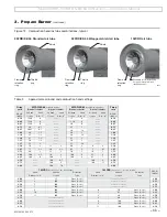
•  Check the air tube length. Verify the usable length of the tube UTL will 

be long enough (see “Mount burner in appliance”).

•  Visually inspect all burner components and wiring.
•  Verify that wiring is intact and leads are securely connected.
•  Verify that all burner components are in good condition.

  Do not install or operate the burner if any component is dam-

aged or if burner does not comply with the specifications of 
Table 1, page 3, and other guidelines of this manual and the 
appliance manual.

Welded-flange burners

1.  Verify the bolt pattern on the appliance chamber matches the flange 

pattern.

2.  Verify the insertion depth (UTL) matches the depth of the appliance 

opening (so the end of the air tube is flush with, or slightly short of, the 
inside surface of the combustion chamber).

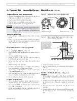
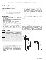
Assemble burner (when required)

Universal (adjustable) flange burners

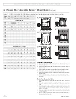
1.  Verify the flange mounting slots line up with the appliance bolts. See 

Figure 2.

2.  Slip the adjustable flange onto the air tube.
3.  Measure the distance from the inside of the combustion chamber to 

the outside of the appliance mounting plate.

4.  Position the universal flange at this distance from the end of the air 

tube.

5.  Tighten the locking screws finger tight.
6.  Insert the air tube/flange assembly into the appliance opening and level 

the air tube with a spirit level. Adjust flange if needed.

7.  The end of the air tube should be flush, or almost flush, with the inside 

of the combustion chamber wall.

8.  Verify  the  air  tube  is  level  and  inserted  the  correct  depth. Adjust  if 

necessary. Then tighten the flange locking screws securely.

9.  Remove the flange/air tube assembly from the opening.

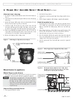
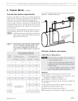
Pedestal mount burners

1.  Check the diameter of the appliance opening. If larger than 4½ inches, 

rebuild the opening so the open is reduced to 4½ inches maximum.

2.  Insert the air tube into the appliance opening as in Figure 3. Do not 

attach air tube to housing yet.

3.  Slide the tube in until the end of the tube is flush with, or up to ¼ inch 

short of, the inside of the combustion chamber.

Figure 2  Universal flange mounting dimensions

Figure 3  Mark insertion depth on air tube when using 

universal flange mounting

2.  Prepare Site • Assemble Burner • Mount Burner 

(continued)

4.  Level the air tube using a spirit level.
5.  Mark the air tube position with a pen or pencil around the circumference 

of the tube.

6.  Remove air tube from the opening.

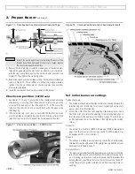
NOTICE — 99FRD/EZ-66 burners firing above  

2.25 GPH

1.  99FRD, EZ-66 burners are shipped with the blank air shutter (behind 

fuel unit) installed. This shutter is suitable only for firing rates up to 2.25 
GPH.

2.  For firing rates over 2.25 GPH, obtain an open type air shutter from 

your Carlin dealer. Remove the blank shutter and replace with the open 
shutter.

3.  The optional open air shutter is suitable for firing rates from 1.50 to 

3.00 GPH.

4.  To change air shutters, remove the burner fuel unit. (The fuel unit holds 

the shutter in place.) Install the correct shutter and replace the fuel 
unit.

Summary of Contents for 102CRD

Page 1: ...formation regarding operation of this burner The burner Instruction Manual is intended only for your service technician The burner and heat exchanger must be inspected and started at least annually by...

Page 2: ...pliance per this manual and the appliance instructions see User s information To keep this manual at or near the burner appliance for ready ac cess by the user and service technician To contact the se...

Page 3: ...ng GPH 0 50 to 3 00 2 00 to 3 50 3 00 to 4 50 Delavan Hollow 60 A Delavan Solid 60 B Hollow 70 A Solid 70 B Hago Hollow 60 H Solid 80 B Hollow 70 H Hago Semi solid 45 SS Monarch Hollow 60 NS Semi soli...

Page 4: ...ning sizes are always given in free area This means after deduction for louver obstruction If you can t find the louver reduction for the grilles used assume free area is 20 of total for wood louvers...

Page 5: ...sary clearances to combustible construction including the correct design of thimbles and insulation where penetrating combustible walls Illustrations A to F in Figure 1 show different chamber configur...

Page 6: ...a diameter at least as larger as the minimum width listed For steel cylinder chambers increase this dimension by from 1 to 4 inches 4 Wing walls are not recommended Corbels can be beneficial to heat...

Page 7: ...t flange if needed 7 The end of the air tube should be flush or almost flush with the inside of the combustion chamber wall 8 Verify the air tube is level and inserted the correct depth Adjust if nece...

Page 8: ...s are intended only for negative overfire pressure For pressur ized firing you must obtain a burner with a welded flange designed for use with the specific appliance Failure to comply could result in...

Page 9: ...ng from the housing Replace the gasket if not in good condition 9 Inspect the ignitor contact clips Clean or replace if necessary to ensure reliable contact with the electrodes Install nozzle check el...

Page 10: ...retention ring clamp is firmly against the nozzle adapter shoulder Set initial burner air settings Combustion head 1 The combustion head adjusting slide controls the spacing between the retention ring...

Page 11: ...15 20 0 20 0 20 0 1 25 1 70 2 2 15 2 60 4 0 4 75 2 3 20 2 3 65 5 5 4 5 80 3 25 3 70 5 10 5 100 4 5 70 4 100 6 45 6 100 6 100 5 100 8 65 7 100 6 7 100 9 100 8 100 11 100 10 102CRD 2 air cone B style a...

Page 12: ...d installed and that the fuel flow is unob structed the oil tank is clean and only 1 or 2 heating oil are supplied Failure to supply a reliable oil flow could result in loss of heat and potential seve...

Page 13: ...lation air openings and vent system o Fuel supply line in good condition and sized designed correctly o Oil tank has oil and oil line valves are open o Wiring installed per burner appliance instructio...

Page 14: ...ents a Check smoke It should be zero on the Bacharach scale b Set the appliance flue damper or barometric draft regulator so the draft or pressure in the vent complies with the appliance manufacturer...

Page 15: ...manual with the user Verify the user is aware of all procedures specified in the manuals Verify user will not store or use combustible liquids or materials or contaminants in the vicinity of the burn...

Page 16: ...21998S 102CRD 7 C Air Tube Combustion Head Assy 22004S 102CRD 9 C Air Tube Combustion Head Assy 21915S 102CRD 11 C Air Tube Combustion Head Assy 4 41000S 110V Ignitor 41000S0CAS 110V Ignitor on Basepl...

Page 17: ...arts continued ITEM PART NO DESCRIPTION 99FRD 100CRD 102CRD 17 70200S Universal Primary w Display 70200 48245S Model 48245 Primary w Smart Ignition 4020002S Model 40200 Primary 30 15 30 5020002S Model...

Page 18: ...time you replace a component or disassemble any part of the burner for service maintenance perform a complete operational test after reassembly to verify the burner operates correctly Failure to veri...

Page 19: ...MN99102 042015 19 Model 99FRD 102CRD EZ 66 Oil Burners Instruction Manual...

Page 20: ...ttempt to use gasoline as a fuel for this burner as it is more combustible and could result in a serious explosion Never attempt to burn refuse or use any fuel other than 1 or 2 heating oil ASTM D396...

Reviews: