background image


 2012 Cargo Floor B.V. Coevorden, Holland 

Versie 01/11-01-2012 

www.cargofloor.com 
[email protected]


Cargo Floor B.V. 
P.O. Box 271 
NL-7740 AG Coevorden 
Phone: +31-(0)524- 

593900  

Fax: +31-(0)524- 

593999 

                         Blz. 52


NL


MONTEREN AFDICHTINGSPROFIEL (SEAL) & EINDKAPPEN 


U legt alle vloerprofielen op de zijkant tegen elkaar, met de groef naar boven. Voordat het afdichtingsprofiel (seal) 
gemonteerd kan worden dient de hiervoor bestemde groef in het vloerprofiel schoon te zijn (eventueel doorblazen met 
lucht).  
Omdat het afdichtingsprofiel (seal) op een rol aangeleverd wordt, dient men, om eenvoudig af te kunnen rollen, de 
positie te bepalen vanaf welke zijde het afdichtingsprofiel (seal) in de groef dient te worden getrokken. De korte lip van 
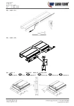
het afdichtingsprofiel (seal) dient altijd naar boven en de lange lip naar beneden te wijzen (zie figuur 22A). Om het 
afdichtingsprofiel (seal) eenvoudig te monteren knipt / snijdt u, na circa 100 mm (wordt handvat), uit het T-stukje 10 
mm materiaal (zie figuur 22A).


Vervolgens plaatst u het T-gedeelte van het afdichtingsprofiel (seal) in de groef en trekt 

door middel van het handvat het afdichtingsprofiel (seal) in het vloerprofiel. U stopt 300 mm voor het einde van het 
vloerprofiel en snijdt het afdichtingsprofiel (seal) vervolgens aan de beginzijde af. Vervolgens plaatst u, afhankelijk van 
de beginzijde van het vloerprofiel en de plaats van de eindkap, de eerste popnagel (zie figuur 22B). Hierna spant u het 
afdichtingsprofiel (seal) op door deze teminste 500 tot 1000 mm (afhankelijk begin verhoogd weerstandsgevoel en de 
lengte van het voertuig) uit te trekken, dit houdt in circa 6 / 10 kg trekkracht. Na het spannen plaatst u conform figuur 
22B


de overige popnagels.  

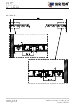
Nu kunnen de eindkappen gemonteerd en vastgezet worden met twee stalen popnagels, (zie figuur 23).


Let op: indien u de eindkappen wenst vast te lassen dient dit voor de montage van het afdichtingsprofiel (seal) 
gedaan te worden.  


GB


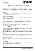
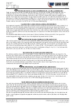
MOUNTING THE SEAL AND END CAPS 


Lay all of the floor profiles on their sides against one another, with the groove facing upwards. The groove in the floor 
profile needs to be clean (if necessary blown through with compressed air) before the seal can be mounted.  
The seal is supplied on a roll. In order to install it simply, one needs to determine from which side of the groove the seal 
needs to be pulled. The short lip of the seal always needs to point upwards and the long lip needs to point downwards 
See figure 22A). To aid the mounting of the seal, snip / cut about 10 mm out of the T-form at about 100 mm from the 
start (this will form a handgrip, see figure 22A). Next, place the T section of the seal in the groove and, using the 
handgrip, pull the seal into the groove in the floor profile. Stop 300 mm before the end of the floor profile, and cut off 
the seal on the start end. Next, depending on the start end of the floor profile and the position of the end cap, place the 
first pop-rivet. (See figure 22B.) Then tension the seal by stretching it by at least 500 to 1000 mm (until you start to feel 
higher resistance and the length of the vehicule), this means about 6 to 10 kg. pulling force. After tensioning the seal 
place the remaining pop-rivets according to figure 22B.  
When this is done the end caps can be mounted and secured with two steel pop-rivets, (see figure 23).  

 
Attention: If you want to secure the end caps by welding, then this needs to be done before mounting the seal. 


D


DICHTUNGSPROFIL (SEAL) UND ENDKAPPEN MONTIEREN 


Legen Sie alle Bodenprofile auf die Seite, gegeneinander, so dass die Nut nach oben weist. Bevor das Dichtungsprofil 
(Seal) montiert werden kann, muss die hierfür bestimmte Nut im Bodenprofil gereinigt sein (ggf. mit Pressluft 
durchblasen).  
Da das Dichtungsprofil (Seal) auf einer Rolle geliefert wird, muss zur Erleichterung des Rollvorgangs die Position 
bestimmt werden, von welcher Seite das Dichtungsprofil (Seal) in die Nut gezogen wird. Die kurze Lippe des 
Dichtungsprofils (Seal) muss dabei immer nach oben und die lange Lippe nach unten zeigen (siehe Abb. 22A). Um das 
Dichtungsprofil (Seal) leicht montieren zu können, kneifen bzw. schneiden Sie nach ca. 100 mm (wird ein Griff) aus 
dem T-Stück 10 mm Material ab (siehe Abb. 22A). Anschließend setzen Sie das T-Stück des Dichtungsprofils (Seal) in 
die Nut und ziehen mit dem Griff das Dichtungsprofil (Seal) in das Bodenprofil. Hören Sie damit 300 mm vor dem 
Ende des Bodenprofils auf und schneiden Sie das Dichtungsprofil (Seal) anschließend an der Startseite ab. Danach 
bringen Sie, abhängig von der Startseite des Bodenprofils und der Position der Endkappe, die erste Hohlniete an (siehe 
Abb. 22B). Spannen Sie anschließend das Dichtungsprofil (Seal), indem Sie es auf mindestens 500 bis 1000 mm 
ausziehen (bis zum Eintreten eines spürbaren Widerstands und die Länge des Fahrzeugs), dies bedeutet etwa 6 bis 10 
kg. Ziehkraft. Nach dem Spannen bringen Sie gemäß Abb. 22b die anderen Hohlnieten an.  
Jetzt können die Endkappen aufgesetzt werden. Befestigen Sie diese mit zwei Hohlnieten aus Stahl (siehe Abb. 23). 
 

Achtung: Wenn Sie die Endkappen schweißen wollen, dann muss dies vor der Montage des Dichtungsprofils 
(Seal) durchgeführt werden.

Summary of Contents for 21-112

Page 1: ...1 01 2012 www cargofloor com info cargofloor com Cargo Floor B V P O Box 271 NL 7740 AG Coevorden Phone 31 0 524 593900 Fax 31 0 524 593999 CARGO FLOOR NL Inbouwinstructies GB Assembly instructions D...

Page 2: ...dan ook zonder voorafgaande schriftelijke toestemming van de uitgever GB No part of this publication may be reproduced stored in a retrieval system or transmitted in any form or by any means electroni...

Page 3: ...ms and text to give clear and simple instructions To ensure the durability and reliability of this revolutionary loading and unloading system it is important that you follow the assembly instructions...

Page 4: ...rventil einstellen 66 Technische gegevens Technical specifications Technische Daten 72 Onderhoudsvoorschriften Maintenance instructions Wartung 75 Belangrijke aanwijzingen Important instructions Wicht...

Page 5: ...ELDEN TYPE Type systeem SYST NR Serie nummer PROD NR Productienummer MAX WP Maximale werkdruk MAX CAP Maximale belading PROD YR Productie jaar GB MEANINGS OF THE FIELDS D BEDEUTUNG DER FELDER TYPE Sys...

Page 6: ...worden meegeleverd dienen of zijn op het voertuig in de nabijheid van de beschreven bediening te worden zijn aangebracht GB These stickers which are delivered with the Cargo Floor systems should or a...

Page 7: ...rdoor deze met kracht vanzelf kunnen openschieten Daarnaast bestaat de mogelijkheid dat een deel van de lading bij het openen er vanzelf uitvalt Gebruik daarom altijd indien aanwezig de pneumatische d...

Page 8: ...ag tot max 23 arbeidslagen per minuut maken Een hoger aantal arbeidsslagen kan tot schade leiden aan het Cargo Floor systeem alsmede aan het voertuig M Het gebruik van te kleine diameters van de hydra...

Page 9: ...altijd zeker indien de lading zachter is dan de hardheid van de vloerprofielen gebruik bij twijfel een beschermkleed of raadpleeg uw leverancier AA Heftruckoverrijdbaarheid In principe zijn alle vloe...

Page 10: ...steem op de volgende manieren worden stopgezet Door het indrukken van de stopknop op de bekabelde afstandbediening Door alle schakelaars in positie 0 te zetten Door de hendel van het besturingsventiel...

Page 11: ...to the P Pressure line min 20mm and the T tank return line min 25mm Also check that the couplings are fully tightened or slid completely into each other IMPORTANT the pressure and return line connect...

Page 12: ...the same hydraulic circuit of the Cargo Floor system P Jamming of the floor profiles caused by the transport of abnormal loads and or the freezing of the floor or of the product to the floor may resul...

Page 13: ...Floor system and the other hydraulic components WARNING TOUCHING OVERHEATED OIL AND COMPONENTS CAN CAUSE BURNS AND INJURIES DD During loading and unloading operations the load should be spread to give...

Page 14: ...INWEIS Die T ren k nnen unter hohem Druck stehen sodass sie mit Kraft von selbst aufspringen Au erdem kann es passieren dass ein Teil der Ladung beim ffnen herausf llt Verwenden Sie darum immer falls...

Page 15: ...herer Takt kann zu Sch den am Cargo Floor System und am Fahrzeug f hren M Die Verwendung von Hydraulikleitungen Verbindungen und Schl uchen mit zu kleinem Durchmesser f hrt zu Sch den N Bei ausbleiben...

Page 16: ...gen Sie Ihren Lieferanten AA Gabelstaplerbefahrbahrkeit Im Prinzip k nnen alle B den mit einem Gabelstapler befahren werden erkundigen Sie sich aber immer zuvor bei Ihrem Lieferanten welche Belastunge...

Page 17: ...System durch eine der nachstehenden Ma nahmen sofort abgeschaltet werden Bet tigen der Stopptaste an der Kabel gesteuerten Fernbedienung Alle Schalter auf 0 stellen Durch die Hebel in die mittlere Po...

Page 18: ...or B V Coevorden Holland Versie 01 11 01 2012 www cargofloor com info cargofloor com Cargo Floor B V P O Box 271 NL 7740 AG Coevorden Phone 31 0 524 593900 Fax 31 0 524 593999 Blz 18 FIG ABB 1A FIG AB...

Page 19: ...lace throughout the entire installation process The piston rod shield must be removed before the system is handed over to the customer IMPORTANT It is not permitted to lift the Cargo Floor system by t...

Page 20: ...2 Cargo Floor B V Coevorden Holland Versie 01 11 01 2012 www cargofloor com info cargofloor com Cargo Floor B V P O Box 271 NL 7740 AG Coevorden Phone 31 0 524 593900 Fax 31 0 524 593999 Blz 20 FIG AB...

Page 21: ...3 H140 bladzijde S4 CF100 SL 2 bladzijde S7 Verder moet er aan de achterzijde van het chassis een plaat gemaakt worden van 300 mm breed welke bevestigt dient te worden op gelijke hoogte van de dwarsli...

Page 22: ...it einer Kopfflanschbreite von maximal 60 mm zu verwenden auf keinen Fall aber weniger als 50 mm Breitere Kopfflanschma e k nnen in diesem Fall durch die Verwendung von hierf r bestimmten speziellen K...

Page 23: ...Coevorden Holland Versie 01 11 01 2012 www cargofloor com info cargofloor com Cargo Floor B V P O Box 271 NL 7740 AG Coevorden Phone 31 0 524 593900 Fax 31 0 524 593999 Blz 23 FIG ABB 4 A FIG ABB 4B A...

Page 24: ...bes need to be securely welded on both sides to each crossbeam with a weld of at least 10 mm length as shown in figure 4B Take care while doing this to ensure that the start and end positions of the t...

Page 25: ...2 Cargo Floor B V Coevorden Holland Versie 01 11 01 2012 www cargofloor com info cargofloor com Cargo Floor B V P O Box 271 NL 7740 AG Coevorden Phone 31 0 524 593900 Fax 31 0 524 593999 Blz 25 FIG AB...

Page 26: ...ssistekening op bladzijde C1 C2 GB POSITIONING THE SYSTEM The hoisting procedures as described on page 9 and 10 need to be studied before placing the Cargo Floor system The Cargo Floor system can now...

Page 27: ...nen Het is van essentieel belang dat het systeem exact in lijn ligt met de kunststof geleidingen waarbij de zuigerstang van de cilinders als referentie dient te worden gebruikt De hartlijn van de zoge...

Page 28: ...es mounted on the crossbeams It is advisable to clamp the Cargo Floor system securely once it is correctly positioned D H HE DES CARGO FLOOR SYSTEMS ANPASSEN UND SYSTEM AUSRICHTEN H he anpassen Das Ca...

Page 29: ...go Floor B V Coevorden Holland Versie 01 11 01 2012 www cargofloor com info cargofloor com Cargo Floor B V P O Box 271 NL 7740 AG Coevorden Phone 31 0 524 593900 Fax 31 0 524 593999 Blz 29 FIG ABB 8 F...

Page 30: ...g Boutverbinding Het Cargo Floor systeem kan desgewenst door een boutverbinding worden bevestigd aan het chassis frame De gaten in het chassis frame dienen concentrisch te zijn met de gaten in het Car...

Page 31: ...eansed of the zinc coating Bolting The Cargo Floor system can if desired be bolted to the chassis frame The holes in the chassis frame need to be concentrically aligned with the holes in the Cargo Flo...

Page 32: ...ird Bolzenverbindung Falls gew nscht kann das Cargo Floor System auch mit einer Bolzenverbindung am Chassis bzw am Rahmen befestigt werden Die L cher im Chassis bzw im Rahmen m ssen konzentrisch mit d...

Page 33: ...uur 9 toont hoe dit eventueel kan gebeuren GB BRACING THE SIDE WALLS The sidewalls of the Cargo Floor system are not supported since no crossbeams are used This can lead to buckling of the sidewalls w...

Page 34: ...740 AG Coevorden Phone 31 0 524 593900 Fax 31 0 524 593999 Blz 34 FIG ABB 11 De arcering geeft het bereik van de standaard drossel aan The shading points out the reach of the standard choke Der Schraf...

Page 35: ...laadstand of blijft in laadstand staan te hoge olieflow geruis lawaai in systeem verhoogde warmteontwikkeling en capaciteitsverlies Flow onafhankelijke drossel Optioneel is een flow onafhankelijke dr...

Page 36: ...using a B control With this the loading unloading direction is determined by a handle D ANSCHLUSS DER HYDRAULIK Das Cargo Floor System ist standardm ig mit einem vormontierten Druckfilter an der Bugbr...

Page 37: ...Schraub die neue Fluss unabh ngige Drossel in den Kanal und setze diese Handfest etwa 50 Nm Schraube den Verschluss wieder in dem Kanal PB und setzte diese Handfest etwa 50Nm Lasse den Boden laufen l...

Page 38: ...oevorden Holland Versie 01 11 01 2012 www cargofloor com info cargofloor com Cargo Floor B V P O Box 271 NL 7740 AG Coevorden Phone 31 0 524 593900 Fax 31 0 524 593999 Blz 38 FIG ABB 13A FIG ABB 13B F...

Page 39: ...jde van het voertuig voorafgaand aan de montage van de aluminium vloerprofielen te worden gemonteerd Zie figuur 13C Advies De overgebleven kunststof geleiders dienen op de laatst twee meter van de vie...

Page 40: ...n bis man ein Klick h rt Abb 13A Kick Twister Als Option ist ein so genannte Kick Twister Abb 13D lieferbar Mit Hilf dieser F hrung ist es m glich die aluminium Bodenprofilen von oben ber der F hrung...

Page 41: ...cargofloor com info cargofloor com Cargo Floor B V P O Box 271 NL 7740 AG Coevorden Phone 31 0 524 593900 Fax 31 0 524 593999 Blz 41 FIG ABB 15 FIG ABB 14A FIG ABB 14B Lasmal Welding jigs Schwei scha...

Page 42: ...n alle aanwezige gaten te worden gebruikt Het is hierbij raadzaam een dwarsligger met een bovenflensbreedte van maximaal 60 mm te gebruiken deze mag niet smaller dan 50 mm zijn Er kunnen tevens afwijk...

Page 43: ...zip der Kunststoff Kammf hrung nicht eingesetzt werden kann dann muss bzw kann die orangefarbene Kunststoff Kammf hrung verwendet werden ACHTUNG Dies gilt nur f r eine Kunststoff Kammf hrung mit einer...

Page 44: ...ij op dat de vloerprofielen korter moeten zijn dan de binnenafmeting van de constructie en let op of de deur binnen of buiten het achterportaal valt Aan de voor en achterzijde van de constructie dient...

Page 45: ...vent damage to the plastic guides To aid mounting the rounded off bevelled side needs to lie in the mounting direction of the vehicle D BODENPROFILE AUF MASS BRINGEN Nachdem die Kunststoff F hrungen m...

Page 46: ...2 Cargo Floor B V Coevorden Holland Versie 01 11 01 2012 www cargofloor com info cargofloor com Cargo Floor B V P O Box 271 NL 7740 AG Coevorden Phone 31 0 524 593900 Fax 31 0 524 593999 Blz 46 FIG AB...

Page 47: ...o Floor B V Coevorden Holland Versie 01 11 01 2012 www cargofloor com info cargofloor com Cargo Floor B V P O Box 271 NL 7740 AG Coevorden Phone 31 0 524 593900 Fax 31 0 524 593999 Blz 47 FIG ABB 19 F...

Page 48: ...sie 01 11 01 2012 www cargofloor com info cargofloor com Cargo Floor B V P O Box 271 NL 7740 AG Coevorden Phone 31 0 524 593900 Fax 31 0 524 593999 Blz 48 FIG ABB 21 C FIG ABB 21 A FIG ABB 21 B FIG AB...

Page 49: ...erzinkboor volgens specificatie G136 HSS DIN 335 C code G13628 0 zie figuur 19 bladzijde 38 Let goed op dat het gat tot op de juiste diepte verzonken wordt de kop van de bout mag nooit boven en onder...

Page 50: ...odenprofil ziehen Sie das Ma des herausragenden Teils von dieser Endabdichtung 10 bis 20 mm ab Bevor Sie mit dem Bohren beginnen m ssen alle Bodenprofile mit der Dichtungsnut in derselben Richtung ver...

Page 51: ...argofloor com info cargofloor com Cargo Floor B V P O Box 271 NL 7740 AG Coevorden Phone 31 0 524 593900 Fax 31 0 524 593999 Blz 51 FIG ABB 22A FIG ABB 22B FIG ABB 23 EINDKAP ENDCAP ENDKAPPE NL Kunsts...

Page 52: ...of the seal snip cut about 10 mm out of the T form at about 100 mm from the start this will form a handgrip see figure 22A Next place the T section of the seal in the groove and using the handgrip pul...

Page 53: ...2 Cargo Floor B V Coevorden Holland Versie 01 11 01 2012 www cargofloor com info cargofloor com Cargo Floor B V P O Box 271 NL 7740 AG Coevorden Phone 31 0 524 593900 Fax 31 0 524 593999 Blz 53 FIG AB...

Page 54: ...need to be well tightened Page 39 fig 21A Very bolt should be fitted with Loctite Loc tite 243 cat o 23286 screw thread locker SECURING THE STATIONARY EDGE PROFILES The stationary profiles always need...

Page 55: ...Floor B V Coevorden Holland Versie 01 11 01 2012 www cargofloor com info cargofloor com Cargo Floor B V P O Box 271 NL 7740 AG Coevorden Phone 31 0 524 593900 Fax 31 0 524 593999 Blz 55 FIG ABB 25A F...

Page 56: ...rbordes Lengte van de plaat tenminste 250 mm breedte en dikte afhankelijk van uw constructie Om deze plaat eenvoudig te kunnen wisselen dient deze binnen het vrije gedeelte van de arbeidsslag van het...

Page 57: ...iel Platz verloren geht dann kann man sich auch f r eine Methode gem Abb 25B entscheiden In diesem Fall werden 6 Bodenprofile des Bodens mit einer Einkerbung versehen Die hierbei entstandenen Fugen we...

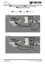
Page 58: ...or B V P O Box 271 NL 7740 AG Coevorden Phone 31 0 524 593900 Fax 31 0 524 593999 Blz 58 NL AANSLUITEN ELEKTRICITEIT GB ELECTRIC CONNECTIONS D ELEKTRISCHE ANSCHLUSSE NL E BEDIENING GB E CONTROL D E BE...

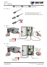
Page 59: ...9 NL B BEDIENING GB B CONTROL D B BEDIENUNG FIG ABB 28 FIG ABB 29 FIG ABB 30 De G02 kabel niet doorknippen grijze connector Do not cut the G02 cable grey connector Nicht die G02 Kabel durchschneiden g...

Page 60: ...This control is equipped with other stickers and certain switching function are not active It is important that the watertight capped cable is mounted but can not and does not have to be connected Th...

Page 61: ...Floor B V Coevorden Holland Versie 01 11 01 2012 www cargofloor com info cargofloor com Cargo Floor B V P O Box 271 NL 7740 AG Coevorden Phone 31 0 524 593900 Fax 31 0 524 593999 Blz 61 FIG ABB 31A F...

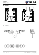
Page 62: ...t number 5165002 see figure 31A mounted on the top edge of the container Many aluminium top edges have this rail already integrated Mount the rails at the same width as the width of the carriage The b...

Page 63: ...fastened to the underside of the bulkhead see figure 32 A section of this tarpaulin about 1250 mm needs to lie on the floor This section of the tarpaulin needs to be fitted with one or more pine wood...

Page 64: ...en aan het systeem oliepeil controleren Benodigde gereedschappen 2x steeksleutel 17 Kruipolie Kopervet Staalborstel Controleer of de draadstang goed in de plunjer van het besturingsventiel bevestigd i...

Page 65: ...Repeat this procedure for the other side N B It is worthwhile spreading some copper grease on the wire rod 1 D DAS EINSTELLEN DER GEWINDESTANGE DES STEUERVENTILES Die Cargo Floor Systeme sind bei der...

Page 66: ...ndingsmotor Filter persfilter type hoge druk 10 micron Artikelnummer 7372005 Persleiding 20 x 2 doorlaat 16 mm Retourleiding 25 x 2 5 doorlaat 20 mm Olie ISO VG 32 Shell Tellus T32 of BP HL2 32 of ESS...

Page 67: ...loerbreedte en lengte in overleg op elke gewenste breedte Aluminium eindkappen t b v vloerprofielen T b v speciale producten zijn volledig gladde profielen leverbaar Vloerdikte 6 8 en 10 mm zie figuur...

Page 68: ...an external combustion engine Filter pressure filter type high pressure 10 micron part number7372005 Pressure piping 20 x 2 feed through 16 mm Return piping 25 x 2 5 feed through 20 mm Oil ISO VG 32...

Page 69: ...ngth in consultation can be any width required Aluminium end caps for floor profiles Completely smooth profiles are available for special products Floor thickness 6 8 and 10 mm See figure 18 page 37 P...

Page 70: ...die Motorleistung am LKW durch ein elektro hydraulisches Aggregat oder durch ein hydraulisches Aggregat mit externem Verbrennungsmotor Filter Druckfilter Typ Hochdruck 10 Micron Ersatzteilnummer 7372...

Page 71: ...20 V 24 V Standard Bodenelemente aus Stahl Bodenelemente mit Stahlbelag Bodenbreite und Lange nach Absprache f r jede gew nschte Breite m glich Aluminium Endkappen f r Bodenprofile F r Spezialprodukte...

Page 72: ...e controleren De kwaliteit van de olie deze dient regelmatig verschoond te worden controle elk jaar Filterelement elk jaar vervangen of frequenter indien nodig Olie elke 2 jaar vervangen of frequenter...

Page 73: ...aspects The quality of the oil this must be cleaned regularly check every year Replace the filter element every year Change the oil every 2 years or more frequently if required The level of oil in th...

Page 74: ...t t des ls dieses muss regelm ig gewechselt werden Kontrolle alle 6 Monate Das Filterelement muss j hrlich ausgetauscht werden lwechsel alle 2 Jahre bei Bedarf h ufiger Der lstand im Tank Um W rmeentw...

Page 75: ...atige gewichtsverdeling op de vloer realiseert Zo niet dan is de kans aanwezig dat de lading blijft staan Plaats bij gebruik van pallets zonodig een houten plank van ca 300 x 18 x 2350 mm multiplex er...

Page 76: ...on scharfkantigem Material wie z B Glas ohne Aufrollmechanismus mit einer Schutzlage Die Abdichtung Bodenprofile werden dabei unn tig stark angegriffen Wenn Sie solche Produkte trotzdem sicher transpo...

Page 77: ...ydraulisch olie gaat over het overdruk ventiel op de trekker of op het systeem Vaststellen of de olie door het overdrukventiel van de trekker of de oplegger gaat Dit is vast te stellen door een duidel...

Page 78: ...keuze lossen Zie punt 6 of punt 7 Zie punt 6 of punt 7 1 Controleer de flow zie pagina 25 11 Vloer beweegt bij keuze lossen met alle drie de groepen tegelijk heen en weer onder hoge druk Capaciteit v...

Page 79: ...net Blocked quick detachable coupling note also the return line Check the quick detachable couplings and unblock if necessary 4a floor does not move in either the loading or unloading direction the hy...

Page 80: ...emergency control 9 floor moves in the loading direction when loading is selected but does not move when unloading is selected Plugs are connected the wrong way round on the solenoids Reverse the plug...

Page 81: ...nnung am Steuerkasten sind aber vorhanden Blockade in der Schnellkupplung Vorsicht Auch bei der R cklaufkupplung Schnellkupplungen berpr fen und gangbar machen 4a Der Boden bewegt sich weder beim Lade...

Page 82: ...n l dt zwar bei Einstellung Laden bei der Einstellung Entladen tut sich aber nichts Stecker an den Spulen sind falsch herum angeschlossen Stecker wechseln 10 Boden bewegt sich nicht bei Einstellung La...

Page 83: ...geval van storingen en of fabricagefouten zijn wij slechts gehouden tot het kosteloos verstrekken van vervangende onderdelen indien Het Cargo Floor systeem overeenkomstig onze inbouwvoorschriften doo...

Page 84: ...responsible for the costless supply of replacement parts if The Cargo Floor system is installed by your trailer builder according to our installation procedures Our maintenance and control procedures...

Page 85: ...fehlern sind wir nur dann f r die kostenlose Stellung von Ersatzteilen verpflichtet wenn das Cargo Floor System gem unseren Einbauvorschriften durch Ihren Karosseriehersteller eingebaut wurde unsere W...

Page 86: ...r B V Coevorden Holland Versie 01 11 01 2012 www cargofloor com info cargofloor com Cargo Floor B V P O Box 271 NL 7740 AG Coevorden Phone 31 0 524 593900 Fax 31 0 524 593999 Blz 86 NL Bijlagen GB Enc...

Page 87: ...0 0 1 6 4 9 1 2 8 2 3 8 1 0 6 5 8 5 6 0 3 6 2 5 1 5 0 0 2 0 0 2 7 1 8 9 0 9 9 0 1 2 1 0 1 2 9 0 1 3 9 0 2 5 9 5 6 0 2 2 9 5 2 2 7 8 2 2 5 0 1 9 5 3 1 2 5 1 9 5 1 2 5 9 0 0 2 0 0 1 4 9 1 6 9 0 8 0 1 5...

Page 88: ...02 1 1 1 2E C a r g oF l o o r B V P O B o x2 7 1 N L 7 7 4 0A GC o e v o r d e n P h o n e 3 1 5 2 4 5 9 3 9 0 0 F a x 3 1 5 2 4 5 9 3 9 9 9 T H I SD R A WI N GI ST H EP R O P E R T YO F C A R G OF L...

Page 89: ...I T H O U TT H E I RWR I T T E NA U T H O R I T Y R E F E R E N T I EMA A T 3 6 1 5 3 8 2 5 9 5 2 7 1 7 9 4 5 6 0 3 1 3 5 1 9 5 1 9 5 2 2 2 7 8 2 2 9 5 2 5 0 1 3 6 9 0 0 1 0 6 5 1 3 6 6 0 1 2 6 0 2 0...

Page 90: ...0L mi n Ma x wo r k i n gp r e s s u r ei np r e s s u r ep i p e Ma x wo r k i n gp r e s s u r ei nr e t u r np i p e 2 2 5b a r 1 0b a r 1 0 0 N m 2 1 0 0 2 2 0 0 2 2 5 0 2 1 4 0 8 9 2 3 4 0 5 0 7...

Page 91: ...C e r t i f i e dc o mp a n y I S O9 0 0 1 2 0 0 8...

Page 92: ......

Page 93: ......

Page 94: ......

Page 95: ......

Page 96: ......

Page 97: ......

Page 98: ......

Page 99: ......

Page 100: ......

Page 101: ......

Page 102: ...UST NOT BE COPIED OR REPRODUCED WITHOUT THEIR WRITTEN AUTHORITY SUBJECT DRAWING NUMBER DRAWN DATE Cargo Floor B V P O Box 271 NL 7740 AG Coevorden Phone 31 524 593900 Fax 31 524 593999 E mail info car...

Page 103: ...Lossen Unload Entladen D charger THIS DRAWING IS THE PROPERTY OF CARGO FLOOR b v AND MUST NOT BE COPIED OR REPRODUCED WITHOUT THEIR WRITTEN AUTHORITY SUBJECT DRAWING NUMBER DRAWN DATE REVISION Page B...

Reviews: