2012 Cargo Floor B.V. Coevorden, Holland
Versie 01/11-01-2012
www.cargofloor.com
[email protected]
Cargo Floor B.V.
P.O. Box 271
NL-7740 AG Coevorden
Phone: +31-(0)524-
593900
Fax: +31-(0)524-
593999
Blz. 49
NL
HET BOREN VAN DE GATEN IN DE VLOERPROFIELEN
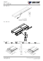
Het boren van de gaten in de vloerdelen dient te gebeuren voordat deze worden geplaatst. Men dient er op te letten
dat door de verschillende afstanden van de bewegende framevoeten in het aandrijfsyteem de gaten versprongen
moeten worden geboord (zie figuur 20, bladzijde 38).
Het opmeten van de gaten dient als volgt te gebeuren:
Controleer of alle 3 de cilinders geheel ingetrokken zijn. U controleert dit als volgt, de uiteinden van de
zuigerstangen mogen niet verder dan 5-10 mm uit de kunststof stanggeleiding steken;
Meet volgens figuur 20 de maat van de binnenzijde achterdeur tot het eerste gat in de vinger die gemonteerd zit
op de bewegende framevoet welke het dichtst bij de cilinders zit. Bij gebruik van een Cargo Floor schuine
eindkap trekt u 50 tot 60 mm (is 40 mm voor de e 10-20 mm extra ruimte) van deze maat af. Bij
gebruik van een andere eindafdichting voor het vloerprofiel trekt u, de maat van het uitstekende deel van deze
eindafdi 10 tot 20 mm af.
Voordat u gaat boren dienen alle vloerprofielen met de afdichtingsgroef in dezelfde richting te liggen.
Let
hierbij speciaal op dat het sluitprofiel (figuur 18, bladzijde 37) met een groef aan twee zijden geboord
wordt op de afstand welke overeenkomt met het gatenpatroon van de eerste of laatste bewegende
framevoet.
Boor vervolgens conform figuur 21 het benodigd aantal vloerprofielen per bewegende framevoet (bij een
standaard 21-planks systeem zijn dit 7 vloerprofielen). Gebruik hiervoor de Cargo Floor boormal,
artikelnummer 9111009.
Met de boormal boort u aan de binnenzijde van het vloerprofiel 4 gaten (voor de Power Speed 6 gaten, zie
inbouwhandleiding Power Speed) van
Ø
4,5 mm voor, waarbij de meegeextrudeerde referentielijn het midden
van het boorgat aangeeft. Daarna boort u vanaf dezelfde richting de gaten op tot rond
Ø
12,5 mm.
Vervolgens dient men de gaten vanaf de bovenzijde te verzinken. Gebruik hiervoor een goede verzinkboor
volgens specificatie G136 HSS DIN 335 C, code G13628.0 (zie figuur 19, bladzijde 38). Let goed op dat het
gat tot op de juiste diepte verzonken wordt, de kop van de bout mag nooit boven en onder het vloerprofiel
uitsteken. Zie figuur 21.
GB
DRILLING THE HOLES IN THE FLOOR PROFILES
The holes in the floor parts need to be drilled before these are placed. One needs to pay attention to the fact that
the holes must be drilled staggered due to the differing distances of the moving frame feet in the drive system (see
figure 20, page 38).
The positions of the holes need to be measured as follows:
Check that all 3 cylinders are completely retracted. You check this by seeing that the ends of the piston rods
protrude no more than 10 mm out of the plastic rod guides;
Measure according to figure 20 the length from the inside of the rear door to the first hole in the finger that is
mounted on the moving frame foot that is closest to the cylinders. If a bevelled Cargo Floor end cap is used
you need to subtract 50 to 60 mm (40 mm for the end cap + 10-20 mm extra space) from this measurement. If
another form of end cap is used for the floor profile then you need to subtract the protruding length of the end
cap plus 10 to 20 mm.
Place all of the floor profiles with the sealing grooves in the same direction before you start drilling.
Pay
special attention to ensuring that the end profiles (with a groove, figure 18 page 37) are drilled on both
sides at a distance that agrees with the pattern of holes for the first or last moving frame foot.
Then drill according to figure 21the necessary number of floor profiles per moving frame foot (this is 7 floor
profiles for a standard 21-plank system), using the Cargo Floor drill jig, part number 9111009.
Drill 4 holes (for the Power Speed 6 holes, see assembly instructions Power Speed) of
Ø
4.5 mm with the aid
of the drill jig on the inside of the floor profile ensuring the centre of the holes line up with the extruded
reference line. Then bore out the holes, from the same direction, to about
Ø
12.5 mm
Next the holes need to be countersunk from the top side using a good countersink bit according to the
specification G136 HSS DIN 335 C, code 13628.0 (figure 19, page 38) Make sure that the hole is countersunk
to the right depth; the bolt head must not stick out above or under the floor profile. See figure 21.

