


COPYRIGHT© 2002 CANON INC.
2000
CANON BOOKLET TRIMMER-A1 REV.0 FEB. 2002
CHAPTER 2 BASIC OPERATIONS
2-34
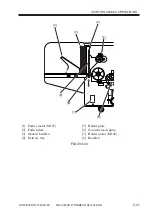
2.4.5 Controlling the Delivery/Stacking Operation
F02-204-07
The holder plate is driven by the holder motor (M106) using the timing belt. The pusher
plate, on the other hand, is driven by the drive of the pusher motor (M107) obtained through
gears. M106 and M107 are driven by the trimmer driver PCB, and are controller by the
trimmer DC controller PCB.
The sensors associated with the operation are as follows: inlet sensor (PS101), delivery
sensor (PS108), upper limit sensor (PS110), lower limit sensor (PS111), pusher sensor
(PS112), stacker full sensor (PS113), and stacker cover sensor (PS114).
5V
IN
GND
5V
IN
GND
5V
IN
GND
5V
IN
GND
5V
IN
GND
5V
IN
GND
5V
IN
GND
DRV
DRV
DRV
DRV
M106_CONT
M106_F/R
M107_CONT
PS110_SIG
PS111_SIG
PS112_SIG
Trimmer DC controller PCB
Trimmer
driver
PCB
PS101
PS114
PS113
PS108
PS110
PS111
PS112
MS3
M107
MS4
M106
Summary of Contents for Two-Knife Booklet Trimmer-A1
Page 129: ...COPYRIGHT 2002 CANON INC 2000 CANON BOOKLET TRIMMER A1 REV 0 FEB 2002 CHAPTER 6 APPENDIX ...
Page 132: ...User Mode COPYRIGHT 2002 CANON INC 2000 CANON BOOKLET TRIMMER A1 REV 0 FEB 2002 ...
Page 141: ...Service Mode COPYRIGHT 2002 CANON INC 2000 CANON BOOKLET TRIMMER A1 REV 0 FEB 2002 ...