


COPYRIGHT© 2002 CANON INC.
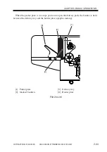
2000
CANON BOOKLET TRIMMER-A1 REV.0 FEB. 2002
CHAPTER 2 BASIC OPERATIONS
2-25
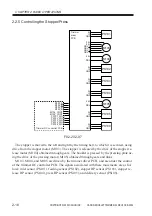
2. Signals
a. Input Signals
(1) PS106_IN (PS106
→
trimmer driver PCB
→
trimmer DC controller PCB);
it is a home position detection signal for the upper blade.
L: at HP
H: not at HP
(2) M102_CONT (trimmer DC controller PCB
→
trimmer driver PCB);
it is an ON/OFF signal for M102 and M108.
L: M102/M108 ON
H: M102/M108 OFF
(3) M102_F/R (trimmer DC controller PCB
→
trimmer driver PCB);
it is a rotation direction switch signal for M102.
L: M102 CCW
H: M102 CW
b. Output signals
(1) DRV (trimmer driver PCB
→
M102);
it is a drive control signal for M102.
The direction of drive current of two signals is switched over to control the direction of
drive of M102.
Summary of Contents for Two-Knife Booklet Trimmer-A1
Page 129: ...COPYRIGHT 2002 CANON INC 2000 CANON BOOKLET TRIMMER A1 REV 0 FEB 2002 CHAPTER 6 APPENDIX ...
Page 132: ...User Mode COPYRIGHT 2002 CANON INC 2000 CANON BOOKLET TRIMMER A1 REV 0 FEB 2002 ...
Page 141: ...Service Mode COPYRIGHT 2002 CANON INC 2000 CANON BOOKLET TRIMMER A1 REV 0 FEB 2002 ...