


COPYRIGHT© 2002 CANON INC.
2000
CANON BOOKLET TRIMMER-A1 REV.0 FEB. 2002
CHAPTER 5 TROUBLESHOOTING
5-1
1 Making Adjustments When Replacing Mechanical/
Electrical Parts
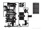
1.1 Trimmer DC Controller PCB
If you have replaced the trimmer DC controller PCB, adjust the brightness of the LCD to
an appropriate level, using VR1; also, shift all bits of DSW3 to OFF position.
F05-101-01
VR1:
for adjusting the intensity of the control panel LCD
Turn clockwise for a darker image; turn counterclockwise for a lighter image.
DSW3: for factory use
Check to make sure that all bits are in OFF position.
LED:
for factory use
1.2 Trimmer Drive PCB
If you have replaced the trimmer drive PCB, perform the following to adjust the sensitiv-
ity for the waste case full condition sensor:
F05-102-01
Turn VR1 fully counterclockwise; then, start turning it clockwise gradually until LED1
goes ON, and turn it clockwise another 2 indexes.
VR1
LED
IC13
J2
J4
J5
DSW3
J3
J1
CN402
CN401
CN404
CN405
CN406
CN403
CN408
CN407
CN409
LED1
VR1
Summary of Contents for Two-Knife Booklet Trimmer-A1
Page 129: ...COPYRIGHT 2002 CANON INC 2000 CANON BOOKLET TRIMMER A1 REV 0 FEB 2002 CHAPTER 6 APPENDIX ...
Page 132: ...User Mode COPYRIGHT 2002 CANON INC 2000 CANON BOOKLET TRIMMER A1 REV 0 FEB 2002 ...
Page 141: ...Service Mode COPYRIGHT 2002 CANON INC 2000 CANON BOOKLET TRIMMER A1 REV 0 FEB 2002 ...