


COPYRIGHT© 2002 CANON INC.
2000
CANON BOOKLET TRIMMER-A1 REV.0 FEB. 2002
CHAPTER 5 TROUBLESHOOTING
5-4
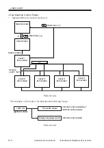
3 Error Code
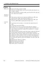
E5A0
Main cause
The cutter motor fails to operate.
1. It does not leave HP within a specific period of time, after the cutter mo-
tor starts to rotate in the forward direction.
2. It does not return to HP within a specific period of time, after the cutter
motor starts to rotate in the forward direction.
3. In the case of 2, it does not return to HP within a specific period of time,
after the cutter motor starts to rotate in the backward direction.
4. The rotation of the fan motor operating in conjunction with the cutter
motor does not stabilize.
Method of
detection
1. The cutter HP sensor does not go OFF within a specific period of time
(2 sec) when it is driven from cutter HP.
2. The cutter HP sensor does not go ON within a specific period of time (5
sec) when it is driven to cutter HP.
3. In the case of 2, the cutter HP sensor does not go ON within a specific
period of time (3 sec) when it is moved to cutter HP by rotating the cut-
ter motor in the backward direction.
4. The fan motor rotation speed lock signal cannot be detected when the
cutter motor is driven.
Action to
take
1. Turn off and on the trimmer (i.e., disconnect and connect the power
cable).
2. Turn off and on the host machine.
3. Execute 'trim motor test' in service mode to check the operation.
4. Check the connection of the harness between the trimmer drive PCB
(connector: CN401) and the DC controller PCB (connector: J1); if
needed, replace the harness.
5. Check the contact of the cutter motor relay harness connected to the
trimmer drive PCB (connector: CN407); if needed, replace the harness.
6. Check the contact of the cutter motor HP sensor relay harness connected
to the trimmer drive PCB (connector: CN408); if needed, replace the
harness.
7. Check the contact of the front door open/closed microswitch MS2 and
the stacker door open/closed microswitch MS3/4; if needed, replace the
harness.
8. Replace the cutter motor HP sensor (PS106).
9. Replace the cutter motor.
10. Replace the trimmer drive PCB.
11. Replace the DC controller PCB.
Summary of Contents for Two-Knife Booklet Trimmer-A1
Page 129: ...COPYRIGHT 2002 CANON INC 2000 CANON BOOKLET TRIMMER A1 REV 0 FEB 2002 CHAPTER 6 APPENDIX ...
Page 132: ...User Mode COPYRIGHT 2002 CANON INC 2000 CANON BOOKLET TRIMMER A1 REV 0 FEB 2002 ...
Page 141: ...Service Mode COPYRIGHT 2002 CANON INC 2000 CANON BOOKLET TRIMMER A1 REV 0 FEB 2002 ...