


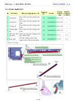


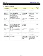


3-4. Grease Application
1 drop = 9 to 18 mg
iX6500 series --- 3. ADJUSTMENT / SETTINGS
TABLE OF CONTENTS
No
Part name
Where to apply grease / oil
Drawing
No.
Grease
Grease
amount
(mg)
Number
of drops x
Location
1 Carriage rail
The surface where the carriage unit
slides
(1)
Floil KG107A 310 to 370
---
2 Carriage rail
The surface where the carriage unit
slides
(2)
Floil KG107A 240 to 280
---
3 Carriage rail
The surface where the carriage unit
slides
(3)
Floil KG107A 240 to 280
---
4
Carriage upper
rail
The surface where the carriage unit
slides
(4)
Floil KG107A 300 to 360
---
5
APP code wheel
gear shaft
APP code wheel gear sliding portion
(the entire surface)
(5)
Floil KG107A 9 to 18
1 x 1
6 Paper guide
LF roller sliding portion on the
opposite side of the home position
(6)
Floil KG107A 18 to 27
2 x 1
40 / 52
Summary of Contents for PIXMA iX6550
Page 19: ...5 Remove the panel cover unit R 1 screw 15 52 ...
Page 21: ...4 Remove the printer unit 6 screws Lift the printer unit Specific screw location 17 52 ...
Page 32: ... 10 Cable wiring and connection 1 Logic board and spur unit 28 52 ...
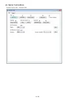
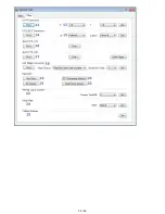
Page 38: ... 2 Service Tool functions Service Tool screen Version 2 000 34 52 ...
Page 39: ...35 52 ...
Page 50: ...4 2 Integrated Inspection Pattern Print Print sample 46 52 ...
Page 51: ...4 3 Ink Absorber Counter Value Print Print sample 4 VERIFICATION AFTER REPAIR 47 52 ...
Page 54: ...50 52 ...