


TABLE OF CONTENTS
1. TROUBLESHOOTING
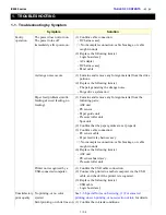
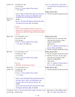
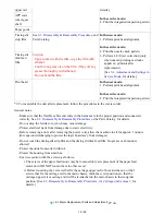
1-1. Troubleshooting by Symptom
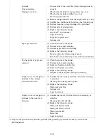
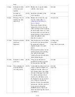
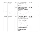
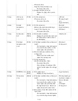
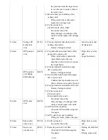
1-2. Operator Call Error Troubleshooting
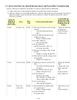
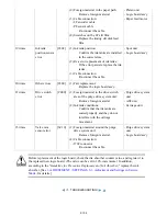
1-3. Service Call Error Troubleshooting
2. REPAIR
2-1. Major Replacement Parts and Adjustment
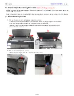
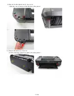
2-2. Disassembly & Reassembly Procedures
(1) External housing removal
(2) Printer unit removal & Ink absorber replacement
(3) Board removal
(4) Carriage unlocking
(5) ASF unit removal
(6) Carriage unit removal
(7) Spur unit and platen unit removal
(8) Purge drive system unit (right plate) and switch system unit (left plate) removal
(9) Engine unit reassembly
(10) Cable wiring and connection
3. ADJUSTMENT / SETTINGS
3-1. Adjustment
3-2. Adjustment and Maintenance in User Mode
3-3. Adjustment and Settings in Service Mode
(1) Service mode operation procedures
(2) Service Tool functions
(3) LF / Eject correction
(4) Ink absorber counter setting
3-4. Grease Application
3-5. Special Notes on Servicing
(1) For smeared printing, uneven printing, or non-ejection of ink
(2) Paper feed motor adjustment
(3) Carriage unit replacement
(4) Ink absorber counter setting
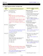
(5) Preventive replacement of ink absorber
(6) Rating label on the bottom case (except China)
4. VERIFICATION AFTER REPAIR
4-1. Standard Inspection Flow
4-2. Integrated Inspection Pattern Print
4-3. Ink Absorber Counter Value Print
iX6500 series
Summary of Contents for PIXMA iX6550
Page 19: ...5 Remove the panel cover unit R 1 screw 15 52 ...
Page 21: ...4 Remove the printer unit 6 screws Lift the printer unit Specific screw location 17 52 ...
Page 32: ... 10 Cable wiring and connection 1 Logic board and spur unit 28 52 ...
Page 38: ... 2 Service Tool functions Service Tool screen Version 2 000 34 52 ...
Page 39: ...35 52 ...
Page 50: ...4 2 Integrated Inspection Pattern Print Print sample 46 52 ...
Page 51: ...4 3 Ink Absorber Counter Value Print Print sample 4 VERIFICATION AFTER REPAIR 47 52 ...
Page 54: ...50 52 ...