

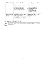


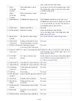


3-2. Adjustment and Maintenance in User Mode
Function
Procedures
Remarks
Nozzle
check
pattern
printing
Perform from the printer driver
Maintenance tab, or via the
Resume/Cancel button.
Set a sheet of plain paper (A4 or Letter) in the rear
tray.
Print head
manual
cleaning
- Cleaning both Black and Color:
Perform from the printer driver
Maintenance tab, or via the
Resume/Cancel button.
- Cleaning Black or Color separately:
Perform from the printer driver
Maintenance tab.
Unclogging of the print head nozzles, and
maintenance to keep the print head conditions good.
If there is a missing portion or white streaks in the
nozzle check pattern printout, perform this cleaning.
Print head
deep
cleaning
Perform from the printer driver
Maintenance tab.
If print head manual cleaning is not effective, perform
this cleaning. Since the deep cleaning consumes more
ink than regular cleaning, it is recommended to
perform deep cleaning only when necessary.
Automatic
print head
alignment
Perform from the printer driver
Maintenance tab, or via the
Resume/Cancel button.
Set a sheet of plain paper (A4 or Letter) in the rear
tray. If the automatic print head alignment is not
effective, perform manual print head alignment.
Manual print
head
alignment
Perform from the printer driver
Maintenance tab.
Set 3 sheets of plain paper (A4 or Letter) in the rear
tray.
Print head
alignment
value
printing
Perform from the printer driver
Maintenance tab.
Confirmation of the current print head alignment
values.
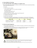
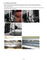
Paper feed
roller
cleaning
Perform from the printer driver
Maintenance tab.
The paper feed rollers rotate while being pushed to the
paper lifting plate. Since the rollers will wear out in
this cleaning, it is recommended that you perform this
only when necessary.
Bottom plate
cleaning
Perform from the printer driver
Maintenance tab, or via the
Resume/Cancel button.
Cleaning of the platen ribs when the back side of
paper gets smeared.
Fold a sheet of plain paper (A4 or Letter) in half
crosswise, then unfold and set it in the rear tray with
the folded ridge facing down.
32 / 52
Summary of Contents for PIXMA iX6550
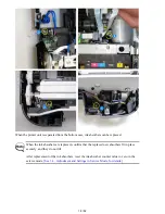
Page 19: ...5 Remove the panel cover unit R 1 screw 15 52 ...
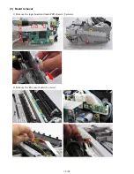
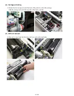
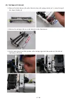
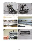
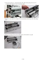
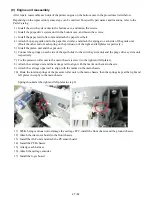
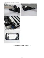
Page 21: ...4 Remove the printer unit 6 screws Lift the printer unit Specific screw location 17 52 ...
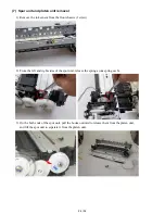
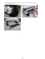
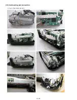
Page 32: ... 10 Cable wiring and connection 1 Logic board and spur unit 28 52 ...
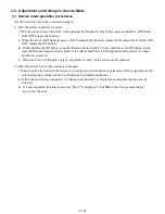
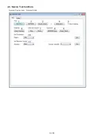
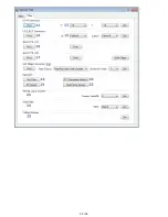
Page 38: ... 2 Service Tool functions Service Tool screen Version 2 000 34 52 ...
Page 39: ...35 52 ...
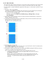
Page 50: ...4 2 Integrated Inspection Pattern Print Print sample 46 52 ...
Page 51: ...4 3 Ink Absorber Counter Value Print Print sample 4 VERIFICATION AFTER REPAIR 47 52 ...
Page 54: ...50 52 ...