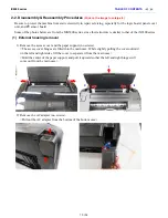


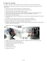


(9) Engine unit reassembly
After repair, reassemble each unit of the printer engine on the bottom case in the procedures listed below.
Depending on the replaced unit, some steps can be omitted. For specific part names and locations, refer to the
Parts Catalog.
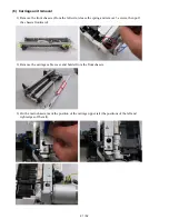
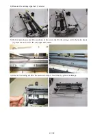
1) Install the switch system unit in the bottom case, and fasten the screws.
2) Install the purge drive system unit in the bottom case, and fasten the screws.
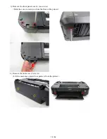
3) Install the paper feed roller unit and attach the paper feed belt.
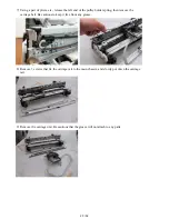
4) Attach the paper guide unit to the paper feed roller, and attach the springs to each side of the guide unit.
(Hook the other end of each spring on the protrusion of the right and left plates respectively.)
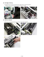
5) Install the platen unit and the spur unit.
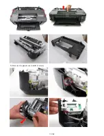
6) Connect the springs on each side of the spur holder to the switch system unit and the purge drive system unit
respectively.
7) Fix the pressure roller unit to the main chassis (screw it to the right and left plates).
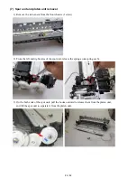
8) Attach the carriage unit and the carriage rail to align with the marks on the main chassis.
9) Attach the carriage upper rail to align with the marks on the main chassis.
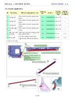
10) Hook the torsion springs of the pressure roller unit to the main chassis, then the springs kept at the right and
left plates in step 6) to the main chassis.
Springs hooked at the right and left plates in step 6):
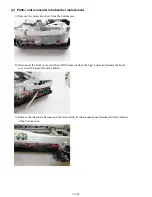
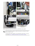
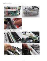
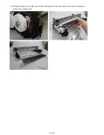
11) While being cautious not to damage the carriage FFC, install the front chassis and the ground chassis.
12) Attach the ink sensor board to the front chassis.
13) Install the ASF unit and attach the PE sensor board.
14) Install the PCB chassis.
15) Arrange each harness.
16) Attach the carriage encoder.
17) Install the logic board.
27 / 52
Summary of Contents for PIXMA iX6550
Page 19: ...5 Remove the panel cover unit R 1 screw 15 52 ...
Page 21: ...4 Remove the printer unit 6 screws Lift the printer unit Specific screw location 17 52 ...
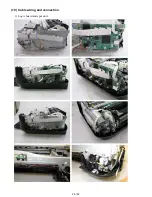
Page 32: ... 10 Cable wiring and connection 1 Logic board and spur unit 28 52 ...
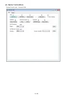
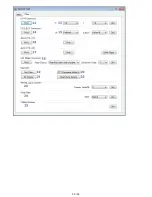
Page 38: ... 2 Service Tool functions Service Tool screen Version 2 000 34 52 ...
Page 39: ...35 52 ...
Page 50: ...4 2 Integrated Inspection Pattern Print Print sample 46 52 ...
Page 51: ...4 3 Ink Absorber Counter Value Print Print sample 4 VERIFICATION AFTER REPAIR 47 52 ...
Page 54: ...50 52 ...