


3. ADJUSTMENT / SETTINGS
3-1. Adjustment
iX6500 series
TABLE OF CONTENTS
Adjustment
Purpose
Method
Approx.
time
Destination settings
(EEPROM settings)
To set the printer destination.
- At logic board replacement
Service Tool
*1
,
Set Destination
section
1 min.
Ink absorber counter
resetting
(EEPROM settings)
To reset the ink absorber counter.
- At ink absorber replacement
Service Tool
*1
,
Main
in the
Clear Ink
Counter
section
1 min.
Ink absorber counter
value setting
(EEPROM settings)
To set the data of the actual ink
amount absorbed in the ink absorber
to the EEPROM.
- At logic board replacement
Service Tool
*1
,
Ink Absorber Counter
section
1 min.
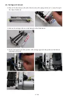
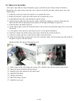
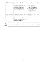
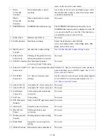
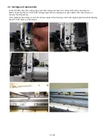
Paper feed motor
position adjustment
To adjust the belt tension.
(Position the paper feed motor so that
the belt is stretched tight.)
- At paper feed motor replacement
Fix the paper feed motor so
that the belt is stretched
tight. (See
3-5. Special
Notes on Servicing, (2)
Paper feed motor
adjustment
, for details.)
5 min.
Automatic print head
alignment
To secure the dot placement
accuracy.
- At print head replacement
- At logic board replacement
- When print quality is not satisfying
Perform automatic print
head alignment in the user
mode.
Recommended for the
iX6500 series.
6 min.
Manual print head
alignment
To secure the dot placement
accuracy.
- At print head replacement
- At logic board replacement
- When print quality is not satisfying
even after automatic print head
alignment is performed
Perform manual print head
alignment in the user mode.
10 min.
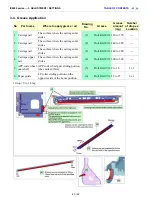
Grease application
To maintain sliding properties of the
applicable portions.
- At carriage unit replacement
- At APP motor replacement
Using a brush, etc., apply
FLOIL KG-107A. (See
3-4.
Grease Application
, for
details.)
1 min.
Ink system function
check
To maintain detection functionality
for presence of the ink tanks and each
ink tank position.
- At logic board replacement
- At spur unit replacement
- At carriage unit replacement
Service Tool
*1
,
Test Print
in the
section
1 min.
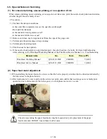
30 / 52
Summary of Contents for PIXMA iX6550
Page 19: ...5 Remove the panel cover unit R 1 screw 15 52 ...
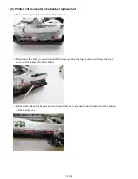
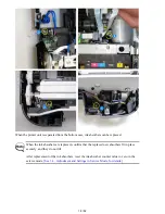
Page 21: ...4 Remove the printer unit 6 screws Lift the printer unit Specific screw location 17 52 ...
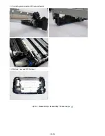
Page 32: ... 10 Cable wiring and connection 1 Logic board and spur unit 28 52 ...
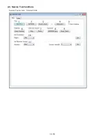
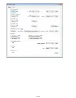
Page 38: ... 2 Service Tool functions Service Tool screen Version 2 000 34 52 ...
Page 39: ...35 52 ...
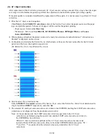
Page 50: ...4 2 Integrated Inspection Pattern Print Print sample 46 52 ...
Page 51: ...4 3 Ink Absorber Counter Value Print Print sample 4 VERIFICATION AFTER REPAIR 47 52 ...
Page 54: ...50 52 ...