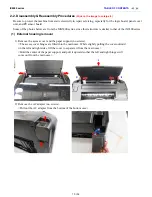
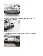

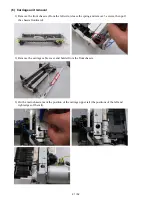

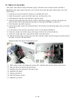


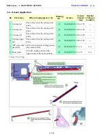

(8) Purge drive system unit (right plate) and switch system unit (left plate) removal
1) Remove the carriage motor cable, and 4 screws from the purge drive system unit.
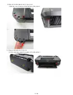
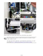
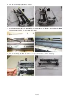
2) Remove 3 screws from the switch system unit.
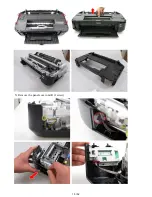
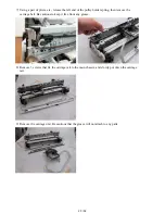
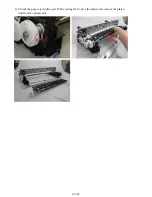
3) Separate the main chassis from the switch system unit and the purge drive system unit.
26 / 52
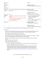
Summary of Contents for PIXMA iX6550
Page 19: ...5 Remove the panel cover unit R 1 screw 15 52 ...
Page 21: ...4 Remove the printer unit 6 screws Lift the printer unit Specific screw location 17 52 ...
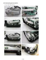
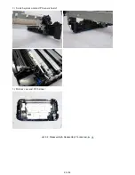
Page 32: ... 10 Cable wiring and connection 1 Logic board and spur unit 28 52 ...
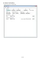
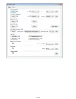
Page 38: ... 2 Service Tool functions Service Tool screen Version 2 000 34 52 ...
Page 39: ...35 52 ...
Page 50: ...4 2 Integrated Inspection Pattern Print Print sample 46 52 ...
Page 51: ...4 3 Ink Absorber Counter Value Print Print sample 4 VERIFICATION AFTER REPAIR 47 52 ...
Page 54: ...50 52 ...