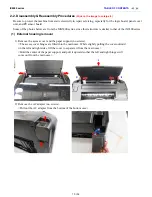
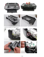

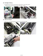
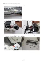

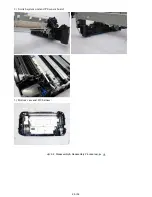


(6) Carriage unit removal
1) Remove the front chassis. (From the left side, release the spring and remove 3 screws, then pull
the chassis frontward).
2) Remove the carriage cable cover and holder from the front chassis.
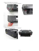
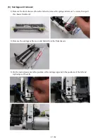
3) On the main chassis, mark the position of the carriage upper rail (the positions of the left and
right edges of the rail).
21 / 52
Summary of Contents for PIXMA iX6550
Page 19: ...5 Remove the panel cover unit R 1 screw 15 52 ...
Page 21: ...4 Remove the printer unit 6 screws Lift the printer unit Specific screw location 17 52 ...
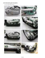
Page 32: ... 10 Cable wiring and connection 1 Logic board and spur unit 28 52 ...
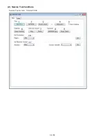
Page 38: ... 2 Service Tool functions Service Tool screen Version 2 000 34 52 ...
Page 39: ...35 52 ...
Page 50: ...4 2 Integrated Inspection Pattern Print Print sample 46 52 ...
Page 51: ...4 3 Ink Absorber Counter Value Print Print sample 4 VERIFICATION AFTER REPAIR 47 52 ...
Page 54: ...50 52 ...