Chapter 5
5-1
5.1 Measurement and Adjustment
5.1.1 Initial Checkup
5.1.1.1 Initial Check
0008-1741
Check the following items before you diagnose malfunction. If any failure is
found, a service engineer is to clear the problem and to give the instruction
to a user.
1) Installation environment
a. The power voltage is -/+10 % of the rated voltage.
b. The printer is securely installed on a level surface.
c. The room temperature is kept between 10 and 30 deg C, and the relative
humidity, between 10 and 80 %.
d. Avoid sites generating ammonia gas, high temperature or high humidity
(near water faucet, kettle, or humidifier), cold places, open flames, dusty
area and sites the wind blows in from the air-conditioning duct.
e. Avoid sites exposed to direct sunlight. If unavoidable, advise the customer
to hang curtains.
f. A well-ventilated place.
g. Make sure that the power cord is inserted to the machine and the outlet
securely.
2) Paper checks
a. The recommended paper for the printer is used.
b. Paper is not damp.
c. Paper is not dirty.
3) Paper sets
a. The amount of paper in the pick-up source is within specifications.
b. Paper is correctly set on the selected pick-up source.
c. The size guides are aligned with paper.
4) Cartridge sets
a. Make sure the EP-87 toner cartridges in each color are set in the printer
properly.
b. Make sure the EP-87 drum cartridge is set in the printer properly.
5) Fixing unit sets
a. Make sure the fixing unit is set in the printer properly.
6) External cover sets
a. Make sure the top cover and memory cover are closed securely.
7) Condensation
During winter, if the printer is brought from a cold place such as a warehouse
into a warm room, condensation will appear inside the printer, causing vari-
ous problems.
Ex.)
a. Condensation in the optical system (four-sided mirror, reflective mirror,
lens, etc.) will result in a light print image.
b. As the photosensitive drum is cold, the resistance of the photoconductive
layer is high; this will lead to incorrect contrast.
If condensation appears, either wipe the parts with dry cloth, or leave the
printer on for 10 to 20 minutes.
If the toner cartridges are opened soon after being moved from a cold
room to a warm room, condensation may appear inside the cartridge and
may cause various problems.
Be sure to instruct the user that it is necessary to leave the printer for one
to two hours at a room temperature to allow it to acclimatize to the
temperature.
5.1.2 Test Printing
5.1.2.1 Test Print
0008-1742
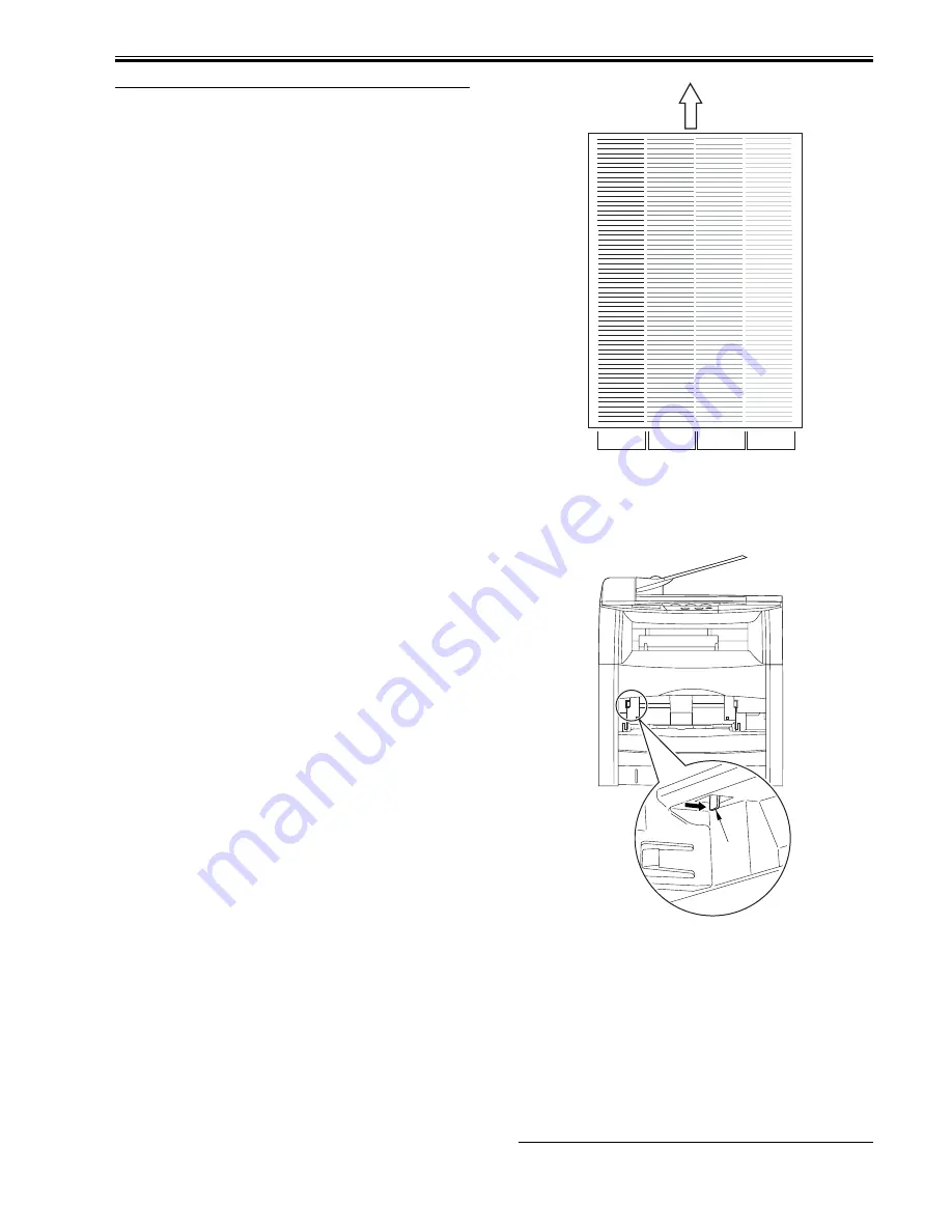
The machine permits printing of engine test prints. Try printing out test
prints so that you may use them for identifying the location of a printer error.
In test printing, the machine prints out the following text pattern in 4 colors
(magenta, cyan, yellow, black):
F-5-1
To Print out Engine Test Prints
- When the machine is in a standby state, press [COLOR START KEY] on
the control panel to generate a color print.
- Open the machine's manual feed tray, and press the test print switch [1]
found on the front left to generate a single test pattern.
F-5-2
5.1.3 Electrical Adjustment
5.1.3.1 Work After Replacing the Laser/Scanner Unit
0008-1740
The flash ROM mounted on the SCNT board retains PWM adjustment set-
tings that are specific to individual laser/scanner units, requiring you to up-
date the settings whenever you have replaced a laser/scanner unit.
Be sure to execute PWM adjustment in service mode, thereby updating the
PWM settings retained in the flash ROM on the SCNT board.
Executing PWM Adjustment
1) Press [MENU] and then [#] to enter service mode.
2) Go to [#TEXT MODE], and press [OK] and [*] in sequence to start [AD-
JUST TEST].
3) Press [1] to start PWM adjustment.
4) When done, see that the indication has changed to "OK".
Yellow
Magenta
Cyan
Black
Feeding Direction
[1]
Summary of Contents for LaserBase MF8180C
Page 1: ...Jan 20 2006 Service Manual MF8100 Series LaserBase MF8180C ...
Page 2: ......
Page 6: ......
Page 20: ...Contents ...
Page 21: ...Chapter 1 PRODUCT DESCRIPTION ...
Page 22: ......
Page 24: ......
Page 32: ......
Page 33: ...Chapter 2 TECHNICAL REFERENCE ...
Page 34: ......
Page 79: ...Chapter 3 DISASSEMBLY AND ASSEMBLY ...
Page 80: ......
Page 90: ......
Page 260: ......
Page 261: ...Chapter 4 MAINTENANCE AND INSPECTION ...
Page 262: ......
Page 264: ......
Page 268: ......
Page 269: ...Chapter 5 TROUBLESHOOTING ...
Page 270: ......
Page 272: ......
Page 286: ......
Page 287: ...Chapter 6 APPENDIX ...
Page 288: ......
Page 290: ......
Page 294: ......
Page 295: ...Jan 20 2006 ...
Page 296: ......


