


Chapter 2
2-9
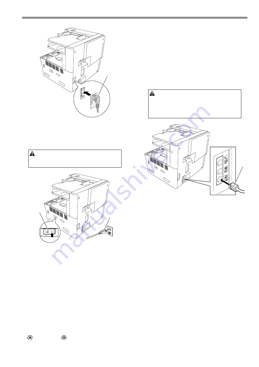
2)Connect the power cord [1] into the AC inlet.
F-2-24
2.2.7 Checking the Image Quality
0016-7410
1)Plug the power cord [1] into the outlet, and then turn on the main power
switch [2].
F-2-25
2)A country/region setting screen appears by the model. Make choices ac-
cording to the environment where the machine is used.
3)Place a document on the document pickup tray, take a copy of it by sup-
plying paper from the cassette or manual feed tray, and check the printed
image. Also perform the following checks:
- Check whether abnormal sound is heard.
- Check the printed images at all preset magnifications.
- Check whether the document is copied normally on the specified
number of sheets.
2.2.8 Setting the Date and Time
0016-7382
1)Press the additional functions key to display the user mode screen.
2)Select "TIMER SETTINGS" and then press the OK.
3)Select "DATE&TIME SETTING".
4)Enter the current date and time with the ten keys.
5)Press the OK to allow the entered date and time to take effect.
2.2.9 Checking the Network Connection
0016-9968
1)Press the following keys to display the service mode screen:
> 2 Key > 8 Key >
2) Select "# REPORT" using the left and right cursor keys, and then press the
OK key.
3) Select "REPORT OUTPUT" using the left and right cursor keys , and then
press the OK.
4)Select "SPEC LIST" using the left and right cursor keys , and then press
the OK.
5) When "SPEC REPORT" is displayed, check that "NETWORK" of "ACT-
IBAT FUNCTION" is set to ON.
6) Contact the system administrator of the customer to make network set-
tings.
2.2.10 Connecting to the Telephone Line
0016-9969
1)Turn off the main power switch of this machine.
2)Connect modular plug at either end of the modular cable [1] to the modular
jack (LINE) at the back of the machine, and connect the other modular
plug to the modular jack on the wall.
F-2-26
3)Turn on the main power switch.
4)Make the minimum settings required to use the fax feature.
a. Registering the User Telephone Number
Additional functions key > [Communications Settings] > [User Settings
(Fax Settings)] > [Uit Telephone #] > Enter the fax No. > [OK]
b. Selecting the Telephone Line Type
Additional functions key > [Communications Settings] > [User Settings
(Fax Settings)] > [Tel Line Type] > Select [Pulse] or [Tone]. > [OK]
5) Conduct a communication test to check the fax feature is implemented
properly.
5-1) Using ten keys, enter the telephone number of a called party who
allows you to conduct the communication test. Send a test
document to check for normal transmission. If the test document
cannot be sent normally, check whether the set telephone line type
is the same as the type of the telephone line connected to this
machine.
5-2) Ask the called party to send a test document to your to check for
normal reception.
Use the specified power supply (rated voltage -/+10% and rated current).
[1]
[2]
[1]
Use the modular cable supplied with the machine. If you use another
modular cable, its length must be within 3 m.
[1]
Summary of Contents for Laser Class 810
Page 2: ......
Page 6: ......
Page 18: ...Contents...
Page 19: ...Chapter 1 Introduction...
Page 20: ......
Page 22: ......
Page 55: ...Chapter 1 1 33...
Page 56: ......
Page 57: ...Chapter 2 Installation...
Page 58: ......
Page 60: ......
Page 76: ......
Page 77: ...Chapter 3 Basic Operation...
Page 78: ......
Page 80: ......
Page 87: ...Chapter 3 3 7...
Page 88: ......
Page 89: ...Chapter 4 Original Exposure System...
Page 90: ......
Page 92: ......
Page 104: ......
Page 105: ...Chapter 5 Original Feeding System...
Page 106: ......
Page 108: ......
Page 126: ...Chapter 5 5 18...
Page 127: ...Chapter 6 Laser Exposure...
Page 128: ......
Page 130: ......
Page 134: ......
Page 135: ...Chapter 7 Image Formation...
Page 136: ......
Page 138: ......
Page 144: ......
Page 145: ...Chapter 8 Pickup and Feed System...
Page 146: ......
Page 148: ......
Page 161: ...Chapter 9 Fixing System...
Page 162: ......
Page 164: ......
Page 175: ...Chapter 10 External and Controls...
Page 176: ......
Page 180: ...Chapter 10 10 2 F 10 2 FM2000 FM1...
Page 197: ...Chapter 11 e Maintenance imageWARE Remote...
Page 198: ......
Page 200: ......
Page 210: ......
Page 211: ...Chapter 12 Maintenance and Inspection...
Page 212: ......
Page 214: ......
Page 216: ......
Page 217: ...Chapter 13 Measurement and Adjustments...
Page 218: ......
Page 220: ......
Page 226: ......
Page 227: ...Chapter 14 Correcting Faulty Images...
Page 228: ......
Page 230: ......
Page 236: ...Chapter 14 14 6 F 14 3 12 6 5 11 3 14 1 10 9 8 7 16 13 15 4 2...
Page 238: ...Chapter 14 14 8...
Page 239: ...Chapter 15 Error Code...
Page 240: ......
Page 242: ......
Page 249: ...Chapter 16 Service Mode...
Page 250: ......
Page 256: ...Chapter 16 16 2...
Page 304: ......
Page 305: ...Chapter 17 Upgrading...
Page 306: ......
Page 308: ......
Page 314: ......
Page 315: ...Chapter 18 Service Tools...
Page 316: ......
Page 317: ...Contents Contents 18 1 Service Tools 18 1 18 1 1 Special Tools 18 1...
Page 318: ......
Page 320: ......
Page 321: ...Mar 26 2010...
Page 322: ......


