


Chapter 16
16-23
If any operation error occurs after changing the setting value, change the setting value to the original one.
16.6.2 <026:Distance from the standby position of CIS to the shading start point>
0016-7945
White shading can be adjusted finely.
Normally, do not change the setting value. If any operation error occurs after changing the setting value, change the setting value to the original one.
16.6.3 <041: Vertical scan start position adjustment (when scanning on a document fed from ADF)>
0016-7947
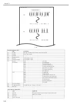
Adjust the position at which vertical scanning of a document fed from the ADF starts. The larger the adjustment value, the narrower the left-side margin of the
image becomes.
16.6.4 <042: Horizontal scan start position adjustment (when scanning on a document fed from ADF)>
0016-7948
Adjust the position at which horizontal scanning of a document fed from the ADF starts. The larger the adjustment value, the narrower the top margin of the image
becomes.
16.6.5 <044: Horizontal scan end position correction (superfine:scanning on ADF)>
0016-7950
Adjust the position at which horizontal scanning of a FAX document scanned in superfine mode ends. The larger the adjustment value, the narrower the bottom
margin of the image becomes.
16.6.6 <045: Horizontal scan end position correction (fine:scanning on ADF)>
0016-7951
Adjust the position at which horizontal scanning of a FAX document scanned in fine mode ends. The larger the adjustment value, the narrower the bottom margin
of the image becomes.
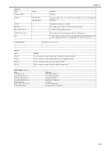
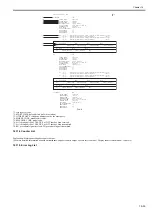
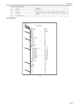
041:
Vertical scan start position adjustment (scanning on ADF)
0 (CIS fix
type)
35 (CIS
shift type)
0-70
one unit=0.1mm
042:
Horizontal scan start position adjustment (scanning on ADF)
241
171-311
one unit=0.1mm
043:
Horizontal scan end position correction (copy:scanning on ADF)
45
0-200
one unit=0.1mm
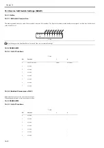
044:
Horizontal scan end position correction (superfine:scanning on ADF)
65
0-200
one unit=0.1mm
045:
Horizontal scan end position correction (fine:scanning on ADF) 80
0-200
one
unit=0.1mm
046:
Horizontal scan end position correction (standard:scanning on ADF)
80
0-200
one unit=0.1mm
047:
Vertical scan magnification correction (scanning on ADF)
16
0-32
one unit=0.1%
048:
Horizontal scan magnification correction (scanning on ADF)
16
0-32
one unit=0.1%
049: - 053:
Not used
054:
Pickup motor speed correction (when the ADF is used)
16
0-32
one unit=0.1%
055: - 082:
Not used
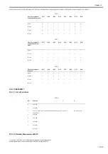
083:
To support the longer size original (1000mm)
6500
6500, 10200
083: - 099:
Not used
100:
Adjustment of the registration loop volume (ADF)
166
126-206
one unit=0.1mm
101: - 192:
Not used
193:
ADF special paper, standardized size: LGL misidentification-ready
0
0 : LEGAL
1 : FOOLSCAP
2 : M_OFFICIO
3 :
A_FOOLSCAP
4 : FOLIO
5 : G_LEGAL
6 : A_OFFICIO
7 : B_OFFICIO
194:
ADF special paper, standardized size: LTR misidentification-ready
0
0 : LTR
1 : G_LTR
2 : A_LTR
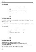
195:
ADF special paper, standardized size: LTR_R misidentification-ready 0
0 : LTR_R
1 : FOOLSCAP
2 : OFFICIO
3 : E_OFFICIO
4 : G_LTR_R
5 : A_LTR_R
196: - 212:
Not used
213:
XYZ correction value (X) of standard white plate
8273
1-9999
214:
XYZ correction value (Y) of standard white plate
8737
1-9999
215:
XYZ correction value (Z) of standard white plate
9427
1-9999
216:-350:
Not used
No.
Function
Default
Setting range
Unit
Summary of Contents for Laser Class 810
Page 2: ......
Page 6: ......
Page 18: ...Contents...
Page 19: ...Chapter 1 Introduction...
Page 20: ......
Page 22: ......
Page 55: ...Chapter 1 1 33...
Page 56: ......
Page 57: ...Chapter 2 Installation...
Page 58: ......
Page 60: ......
Page 76: ......
Page 77: ...Chapter 3 Basic Operation...
Page 78: ......
Page 80: ......
Page 87: ...Chapter 3 3 7...
Page 88: ......
Page 89: ...Chapter 4 Original Exposure System...
Page 90: ......
Page 92: ......
Page 104: ......
Page 105: ...Chapter 5 Original Feeding System...
Page 106: ......
Page 108: ......
Page 126: ...Chapter 5 5 18...
Page 127: ...Chapter 6 Laser Exposure...
Page 128: ......
Page 130: ......
Page 134: ......
Page 135: ...Chapter 7 Image Formation...
Page 136: ......
Page 138: ......
Page 144: ......
Page 145: ...Chapter 8 Pickup and Feed System...
Page 146: ......
Page 148: ......
Page 161: ...Chapter 9 Fixing System...
Page 162: ......
Page 164: ......
Page 175: ...Chapter 10 External and Controls...
Page 176: ......
Page 180: ...Chapter 10 10 2 F 10 2 FM2000 FM1...
Page 197: ...Chapter 11 e Maintenance imageWARE Remote...
Page 198: ......
Page 200: ......
Page 210: ......
Page 211: ...Chapter 12 Maintenance and Inspection...
Page 212: ......
Page 214: ......
Page 216: ......
Page 217: ...Chapter 13 Measurement and Adjustments...
Page 218: ......
Page 220: ......
Page 226: ......
Page 227: ...Chapter 14 Correcting Faulty Images...
Page 228: ......
Page 230: ......
Page 236: ...Chapter 14 14 6 F 14 3 12 6 5 11 3 14 1 10 9 8 7 16 13 15 4 2...
Page 238: ...Chapter 14 14 8...
Page 239: ...Chapter 15 Error Code...
Page 240: ......
Page 242: ......
Page 249: ...Chapter 16 Service Mode...
Page 250: ......
Page 256: ...Chapter 16 16 2...
Page 304: ......
Page 305: ...Chapter 17 Upgrading...
Page 306: ......
Page 308: ......
Page 314: ......
Page 315: ...Chapter 18 Service Tools...
Page 316: ......
Page 317: ...Contents Contents 18 1 Service Tools 18 1 18 1 1 Special Tools 18 1...
Page 318: ......
Page 320: ......
Page 321: ...Mar 26 2010...
Page 322: ......


