


Introduction
The following rules apply throughout this Service Manual:
1. Each chapter contains sections explaining the purpose of specific functions and the relationship between electrical and mechanical systems with refer-
ence to the timing of operation.
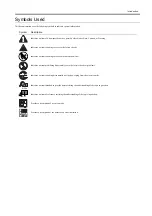
In the diagrams,
represents the path of mechanical drive; where a signal name accompanies the symbol , the arrow
indicates the
direction of the electric signal.
The expression "turn on the power" means flipping on the power switch, closing the front door, and closing the delivery unit door, which results in
supplying the machine with power.
2. In the digital circuits, '1'is used to indicate that the voltage level of a given signal is "High", while '0' is used to indicate "Low".(The voltage value, how-
ever, differs from circuit to circuit.) In addition, the asterisk (*) as in "DRMD*" indicates that the DRMD signal goes on when '0'.
In practically all cases, the internal mechanisms of a microprocessor cannot be checked in the field. Therefore, the operations of the microprocessors
used in the machines are not discussed: they are explained in terms of from sensors to the input of the DC controller PCB and from the output of the
DC controller PCB to the loads.
The descriptions in this Service Manual are subject to change without notice for product improvement or other purposes, and major changes will be com-
municated in the form of Service Information bulletins.
All service persons are expected to have a good understanding of the contents of this Service Manual and all relevant Service Information bulletins and be
able to identify and isolate faults in the machine."
Summary of Contents for Laser Class 810
Page 2: ......
Page 6: ......
Page 18: ...Contents...
Page 19: ...Chapter 1 Introduction...
Page 20: ......
Page 22: ......
Page 55: ...Chapter 1 1 33...
Page 56: ......
Page 57: ...Chapter 2 Installation...
Page 58: ......
Page 60: ......
Page 76: ......
Page 77: ...Chapter 3 Basic Operation...
Page 78: ......
Page 80: ......
Page 87: ...Chapter 3 3 7...
Page 88: ......
Page 89: ...Chapter 4 Original Exposure System...
Page 90: ......
Page 92: ......
Page 104: ......
Page 105: ...Chapter 5 Original Feeding System...
Page 106: ......
Page 108: ......
Page 126: ...Chapter 5 5 18...
Page 127: ...Chapter 6 Laser Exposure...
Page 128: ......
Page 130: ......
Page 134: ......
Page 135: ...Chapter 7 Image Formation...
Page 136: ......
Page 138: ......
Page 144: ......
Page 145: ...Chapter 8 Pickup and Feed System...
Page 146: ......
Page 148: ......
Page 161: ...Chapter 9 Fixing System...
Page 162: ......
Page 164: ......
Page 175: ...Chapter 10 External and Controls...
Page 176: ......
Page 180: ...Chapter 10 10 2 F 10 2 FM2000 FM1...
Page 197: ...Chapter 11 e Maintenance imageWARE Remote...
Page 198: ......
Page 200: ......
Page 210: ......
Page 211: ...Chapter 12 Maintenance and Inspection...
Page 212: ......
Page 214: ......
Page 216: ......
Page 217: ...Chapter 13 Measurement and Adjustments...
Page 218: ......
Page 220: ......
Page 226: ......
Page 227: ...Chapter 14 Correcting Faulty Images...
Page 228: ......
Page 230: ......
Page 236: ...Chapter 14 14 6 F 14 3 12 6 5 11 3 14 1 10 9 8 7 16 13 15 4 2...
Page 238: ...Chapter 14 14 8...
Page 239: ...Chapter 15 Error Code...
Page 240: ......
Page 242: ......
Page 249: ...Chapter 16 Service Mode...
Page 250: ......
Page 256: ...Chapter 16 16 2...
Page 304: ......
Page 305: ...Chapter 17 Upgrading...
Page 306: ......
Page 308: ......
Page 314: ......
Page 315: ...Chapter 18 Service Tools...
Page 316: ......
Page 317: ...Contents Contents 18 1 Service Tools 18 1 18 1 1 Special Tools 18 1...
Page 318: ......
Page 320: ......
Page 321: ...Mar 26 2010...
Page 322: ......


