


Chapter 8
8-2
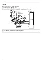
8.2 Detection Jams
8.2.1 Jam Detection Outline
8.2.1.1 Outline
0016-7800
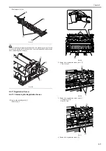
The machine is equipped with 3 jam sensors and 1 jam switch used to motor the movement of paper.
The presence/absence of paper or of a jam is checked at such times as programmed in advance in the CPU of the DC controller PCB and in relation to the presence/
absence of paper over a specific sensor at a given time. If the machine detects a jam, it will turn off the main
motor (M1), and will indicate a jam message in the control panel.
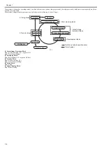
F-8-2
T-8-2
8.2.1.2 Types of Jams
0016-7801
The machine groups jams into 7 types. When a jam occurs, be sure to remove it, and start over the operation.
Pickup Delay Jam
After execution of a pickup retry, the registration sensor (SR11) does not detect the leading edge of paper within a specific period of time. Or after the duplex drive
solenoid (SL1) is on, the registration sensor (SR11) does not detect the leading edge of paper within a specific period of time.
Delivery Sensor Delay Jam
After the registration sensor (SR11) has detected the leading edge of paper, the delivery sensor (SR5) does not detect the leading edge of paper within a specific
period of time.
Pickup Stationary Jam
After the registration sensor (SR11) has detected the leading edge of paper, the registration sensor (SR11) does not detect the trailing edge of paper within a specific
period of time.
Delivery Sensor Stationary Jam
After the registration sensor (SR11) has detected the trailing edge of paper, the delivery sensor (SR5) does not detect the trailing edge of paper within a specific
period of time.
Wound Paper Jam at Fuser
Symbol
Name
SR5
Delivey sensor
SR9
Cassette paper sensor
SR11
Registration sensor
SW2
Interlock switch
SR9
SR11
SR5
SW2
Summary of Contents for Laser Class 810
Page 2: ......
Page 6: ......
Page 18: ...Contents...
Page 19: ...Chapter 1 Introduction...
Page 20: ......
Page 22: ......
Page 55: ...Chapter 1 1 33...
Page 56: ......
Page 57: ...Chapter 2 Installation...
Page 58: ......
Page 60: ......
Page 76: ......
Page 77: ...Chapter 3 Basic Operation...
Page 78: ......
Page 80: ......
Page 87: ...Chapter 3 3 7...
Page 88: ......
Page 89: ...Chapter 4 Original Exposure System...
Page 90: ......
Page 92: ......
Page 104: ......
Page 105: ...Chapter 5 Original Feeding System...
Page 106: ......
Page 108: ......
Page 126: ...Chapter 5 5 18...
Page 127: ...Chapter 6 Laser Exposure...
Page 128: ......
Page 130: ......
Page 134: ......
Page 135: ...Chapter 7 Image Formation...
Page 136: ......
Page 138: ......
Page 144: ......
Page 145: ...Chapter 8 Pickup and Feed System...
Page 146: ......
Page 148: ......
Page 161: ...Chapter 9 Fixing System...
Page 162: ......
Page 164: ......
Page 175: ...Chapter 10 External and Controls...
Page 176: ......
Page 180: ...Chapter 10 10 2 F 10 2 FM2000 FM1...
Page 197: ...Chapter 11 e Maintenance imageWARE Remote...
Page 198: ......
Page 200: ......
Page 210: ......
Page 211: ...Chapter 12 Maintenance and Inspection...
Page 212: ......
Page 214: ......
Page 216: ......
Page 217: ...Chapter 13 Measurement and Adjustments...
Page 218: ......
Page 220: ......
Page 226: ......
Page 227: ...Chapter 14 Correcting Faulty Images...
Page 228: ......
Page 230: ......
Page 236: ...Chapter 14 14 6 F 14 3 12 6 5 11 3 14 1 10 9 8 7 16 13 15 4 2...
Page 238: ...Chapter 14 14 8...
Page 239: ...Chapter 15 Error Code...
Page 240: ......
Page 242: ......
Page 249: ...Chapter 16 Service Mode...
Page 250: ......
Page 256: ...Chapter 16 16 2...
Page 304: ......
Page 305: ...Chapter 17 Upgrading...
Page 306: ......
Page 308: ......
Page 314: ......
Page 315: ...Chapter 18 Service Tools...
Page 316: ......
Page 317: ...Contents Contents 18 1 Service Tools 18 1 18 1 1 Special Tools 18 1...
Page 318: ......
Page 320: ......
Page 321: ...Mar 26 2010...
Page 322: ......


