


Chapter 13
13-4
13.4 ADF
13.4.1 Outline
13.4.1.1 Outline
0017-5663
This machine has the following adjustment items. Make the necessary ad-
justments after replacing each part.
T-13-3
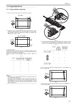
13.4.1.2 Preparing a Test Sheet for Adjustment
0017-5664
Preparing a Test Sheet for Adjustment
F-13-6
F-13-7
13.4.2 Adjusting the Electrical System
13.4.2.1 Adjusting the Magnification
0017-5950
1) Create a test chart, load it in the ADF, and make a copy of it. This copy is
called copy A.
2) Compare the longitudinal image length on the test chart with that on copy
A. If required, make an adjustment in the service mode.
(A4-size paper: 277 +/-1mm LTR paper: 59 +/-1mm)
Image on copy A is shorter. -> Increase the value (or reduce the stream read-
ing speed).
Image on copy A is longer. -> Decrease the value (or increase the stream
reading speed).
3) Enter the service mode.
Sequentially press the additional functions key, 2 key, 8 key, and additional
functions key on the operation panel of the host machine.
4) Using the arrow keys on the operation panel, display "#SCAN".
5) Press the OK key.
6) Using the arrow keys on the operation panel, display "#SCAN NUMER-
IC".
7) Press the OK key.
8) Using the arrow keys, select "48".
9) Using the numeric keys, change the value to determine the optimum value.
Next, press the OK key. (Default: 32)
Do not change the adjustment value excessively.
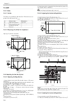
13.4.2.2 Adjusting the Horizontal Registration
0017-5952
1) Load the test chart in the ADF and make a copy of it.
2) Compare the horizontal registration of the chart with that of the copy. If
required, make an adjustment.
The specified horizontal registration is 10mm +/-2mm.
F-13-8
1) Load the test chart in the ADF and make a copy of it.
2) Compare the horizontal registration of the chart with that of the copy. If
required, make an adjustment.
The specified horizontal registration is 10mm +/-2mm.
3) Enter the service mode.
Sequentially press the Additional functions key, 2 key, 8 key, and Additional
functions key on the operation panel of the host machine.
4) Using the arrow keys on the operation panel, display "#SCAN".
5) Press the OK key.
6) Using the arrow keys on the operation panel, display "#SCAN NUMER-
IC".
7) Press the OK key.
8) Using the arrow keys, select "41".
9) Using the numeric keys, change the value to determine the optimum value.
Next, press the OK key. (Default: 35)
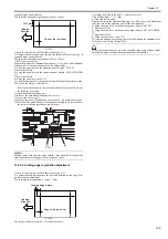
If the registration cannot be set to the specified value using software, use
the following procedure:
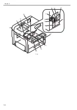
1) Open the document pickup tray.
2) Remove the document pickup tray lower cover.
3) Loosen the one screw [1] and move the slide guide forward or backward
according to the scale calibrated in mm so that the registration is within
spec.
F-13-9
MEMO:
Making copies with the slide guide shifted 1 mm upward will increase the
right registration (on the upper side of paper) by 1 mm.
13.4.2.3 Adjusting the Horizontal Registration
0017-8993
1) Load the test chart in the ADF and make a copy of it.
2) Compare the horizontal registration of the chart with that of the copy. If
No.
Adjustment type
Replaced parts
[1]
Magnification adjustment
Motor/roller
[2]
Side registration adjustment
-
[3]
Leading edge registration
adjustment
-
10mm
10mm
10mm
10mm
<Using A4 Paper>
Draw straight lines.
(feeding
direction)
10mm
210mm
297mm
10mm
10mm
10mm
10mm
<Using LTR Paper>
Draw straight lines.
(feeding
direction)
10mm
216mm
279mm
Copy of the test sheet
(feeding
direction)
10±2mm
[1]
Summary of Contents for Laser Class 810
Page 2: ......
Page 6: ......
Page 18: ...Contents...
Page 19: ...Chapter 1 Introduction...
Page 20: ......
Page 22: ......
Page 55: ...Chapter 1 1 33...
Page 56: ......
Page 57: ...Chapter 2 Installation...
Page 58: ......
Page 60: ......
Page 76: ......
Page 77: ...Chapter 3 Basic Operation...
Page 78: ......
Page 80: ......
Page 87: ...Chapter 3 3 7...
Page 88: ......
Page 89: ...Chapter 4 Original Exposure System...
Page 90: ......
Page 92: ......
Page 104: ......
Page 105: ...Chapter 5 Original Feeding System...
Page 106: ......
Page 108: ......
Page 126: ...Chapter 5 5 18...
Page 127: ...Chapter 6 Laser Exposure...
Page 128: ......
Page 130: ......
Page 134: ......
Page 135: ...Chapter 7 Image Formation...
Page 136: ......
Page 138: ......
Page 144: ......
Page 145: ...Chapter 8 Pickup and Feed System...
Page 146: ......
Page 148: ......
Page 161: ...Chapter 9 Fixing System...
Page 162: ......
Page 164: ......
Page 175: ...Chapter 10 External and Controls...
Page 176: ......
Page 180: ...Chapter 10 10 2 F 10 2 FM2000 FM1...
Page 197: ...Chapter 11 e Maintenance imageWARE Remote...
Page 198: ......
Page 200: ......
Page 210: ......
Page 211: ...Chapter 12 Maintenance and Inspection...
Page 212: ......
Page 214: ......
Page 216: ......
Page 217: ...Chapter 13 Measurement and Adjustments...
Page 218: ......
Page 220: ......
Page 226: ......
Page 227: ...Chapter 14 Correcting Faulty Images...
Page 228: ......
Page 230: ......
Page 236: ...Chapter 14 14 6 F 14 3 12 6 5 11 3 14 1 10 9 8 7 16 13 15 4 2...
Page 238: ...Chapter 14 14 8...
Page 239: ...Chapter 15 Error Code...
Page 240: ......
Page 242: ......
Page 249: ...Chapter 16 Service Mode...
Page 250: ......
Page 256: ...Chapter 16 16 2...
Page 304: ......
Page 305: ...Chapter 17 Upgrading...
Page 306: ......
Page 308: ......
Page 314: ......
Page 315: ...Chapter 18 Service Tools...
Page 316: ......
Page 317: ...Contents Contents 18 1 Service Tools 18 1 18 1 1 Special Tools 18 1...
Page 318: ......
Page 320: ......
Page 321: ...Mar 26 2010...
Page 322: ......


