Chapter 7
7-193
7.11.22.4
Removing the DC
Controller Box
0004-1068
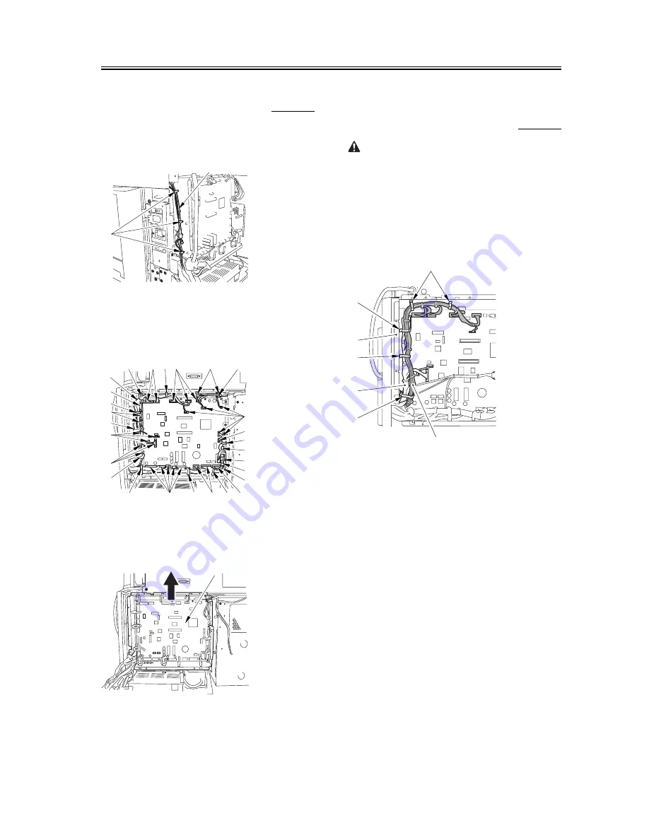
1) Open the 3 cable guides [1], and free the harness
[2].
F-7-669
2) Disconnect the 33 connectors [1], and open that 13
cable guides [2]; then, free the harness [3].
F-7-670
3) Lift the DC controller box [1] to detach.
F-7-671
7.11.22.5
Points to Note When
Mounting the DC Controller
Box
0005-7220
During assembly work, be sure to connect the
harness to the DC controller PCB as follows:
Connect the connector of the harness [1] first, and
then the other harness [2].
Fix the harnesses [1] [2] in place using the wire
saddle [3] so that the harness [1] is on the left side of
the harness [2].
F-7-672
Supplementary Information:
If the harness [1] is away from the side plate [4] of the
DC controller box, wrong detection (E0700102) of
the ITB home position tends to occur because of
noise.
[1]
[2]
[1]
[1]
[2]
[1]
[2]
[1]
[1]
[2]
[1]
[2]
[3]
[2]
[2]
[2]
[1]
[1]
[3]
[1]
[1]
[3]
[2]
[1]
[1]
[2]
[2]
[2] [1]
[1]
[2]
[1]
[3]
[3]
[3]
[3]
[4]
Summary of Contents for iR C6800 Series
Page 1: ...Apr 6 2004 Service Manual iR C6800 Series iR C6800C ...
Page 2: ......
Page 6: ......
Page 21: ...Chapter 1 Introduction ...
Page 22: ......
Page 24: ......
Page 55: ...Chapter 2 Installation ...
Page 56: ......
Page 115: ...Chapter 3 Basic Operation ...
Page 116: ......
Page 118: ......
Page 129: ...Chapter 4 Main Controller ...
Page 130: ......
Page 178: ...Chapter 4 4 46 ...
Page 179: ...Chapter 5 Original Exposure System ...
Page 180: ......
Page 234: ...Chapter 5 5 52 ...
Page 235: ...Chapter 6 Laser Exposure ...
Page 236: ......
Page 238: ......
Page 257: ...Chapter 7 Image Formation ...
Page 258: ......
Page 562: ...Chapter 7 7 296 ...
Page 563: ...Chapter 8 Pickup Feeding System ...
Page 564: ......
Page 614: ...Chapter 8 8 46 F 8 49 10 9 12 11 5 5 4 4 3 5 1 2 1 2 3 1 2 3 4 1 2 3 4 5 ...
Page 616: ...Chapter 8 8 48 F 8 51 2 1 3 3 3 2 1 1 2 1 2 3 5 6 7 8 ...
Page 660: ...Chapter 8 8 92 ...
Page 661: ...Chapter 9 Fixing System ...
Page 662: ......
Page 728: ...Chapter 9 9 64 ...
Page 729: ...Chapter 10 Externals and Controls ...
Page 730: ......
Page 734: ...Contents ...
Page 742: ...Chapter 10 10 8 F 10 2 FM12 FM11 FM1 FM2 FM4 FM3 FM6 FM7 FM9 FM8 FM5 FM13 FM14 FM10 ...
Page 787: ...Chapter 11 Maintenance and Inspection ...
Page 788: ......
Page 790: ......
Page 815: ...Chapter 12 Standards and Adjustments ...
Page 816: ......
Page 868: ...Chapter 12 12 50 ...
Page 869: ...Chapter 13 Correcting Faulty Images ...
Page 870: ......
Page 882: ...Chapter 13 13 10 13 3 Troubleshooting ...
Page 898: ...Chapter 13 13 26 Image Sample F 13 13 ...
Page 900: ...Chapter 13 13 28 Image Sample F 13 15 ...
Page 929: ...Chapter 13 13 57 Image Sample F 13 45 ...
Page 932: ...Chapter 13 13 60 Image Sample image of a specific color is too light F 13 47 ...
Page 933: ...Chapter 13 13 61 image of a specific color is too dark F 13 48 ...
Page 934: ...Chapter 13 13 62 image is too light overall F 13 49 ...
Page 966: ...Chapter 13 13 94 F 13 70 PS65 PS38 PS39 PS46 PS44 PS45 PS52 PS53 PS58 PS59 PS37 ...
Page 968: ...Chapter 13 13 96 F 13 71 SW14 SW15 SW12 SW11 SW1 SW13 SW2 SW3 ...
Page 980: ...Chapter 13 13 108 ...
Page 981: ...Chapter 14 Self Diagnosis ...
Page 982: ......
Page 1051: ...Chapter 15 Service Mode ...
Page 1052: ......
Page 1302: ...Chapter 15 15 238 ...
Page 1303: ...Chapter 16 Upgrading ...
Page 1304: ......
Page 1306: ......
Page 1395: ...Chapter 17 Service Tools ...
Page 1396: ......
Page 1397: ...Contents Contents 17 1 Special Tools 17 1 17 2 Solvents and Oils 17 3 ...
Page 1398: ......
Page 1402: ...Chapter 17 17 4 ...
Page 1403: ...Apr 6 2004 ...
Page 1404: ......


