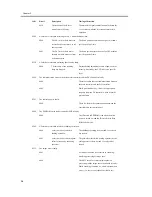


Chapter 3
3-16
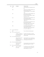
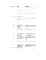
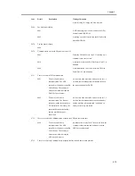
0004
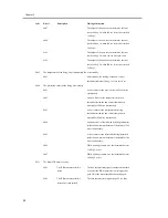
There is a fault in data
communication. The cassette
pedestal controller or the finisher
controller PCB is faulty.
The communication between the finisher and the
machine is disrupted.
E716
There is a fault in the communication between the cassette pedestal and the printer unit.
0000
There is a fault in data
communication. The DC
controller or the cassette pedestal
controller PCB is faulty.
An attempt at recovery fails for 2 sec or more after
the communication between the cassette pedestal
and the machine has failed.
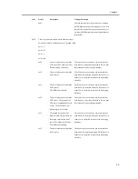
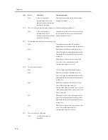
E717
The communication with the NE controller is faulty.
0000
The communication with the NE controller is
disrupted and is not resumed within 3 sec thereafter.
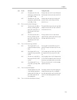
0001
While the new controller is starting up, an error
occurs. (Detection was normal before the power has
been turned off, but detection fails when the power
is turned o)
0002
While the new controller is in operation, an IPC
error occurs (The system assumes that IPC
communication cannot be restored.)
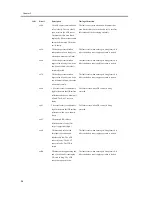
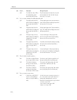
E719
The coin vendor is faulty.
0000
The coin vendor cannot be detected at startup.
0001
While the coin manager is starting up, an error
occurs. (Detection was normal before the power has
been turned off, but detection fails when the power
is turned on.)
0002
While the coin manager is in operation, an error
occurs. (The system assumes that IPC
communication cannot be restored, there is an open
circuit for the pickup/delivery signal, or there is an
illegal connection.)
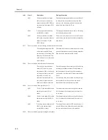
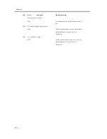
0011
While the mew card reader is starting up, an error
occurs. (Detection is normal before the power has
been turned off, but detection fails when the power
is turned on.)
0012
While the new card reader is in operation, an error
occurs. (The system assumes that IPC
communication cannot be restored.)
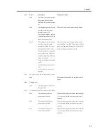
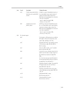
E731
There is a fault in the UFR board.
3000
The UFR board cannot be
recognized.
Code
Detail
Description
Timing of detection
Summary of Contents for iR C3200 Series
Page 1: ...Dec 3 2004 Portable Manual iR C3200 Series iR C3220N PRT ...
Page 2: ......
Page 6: ......
Page 10: ......
Page 11: ...Chapter 1 Maintenance and Inspection ...
Page 12: ......
Page 14: ......
Page 22: ...Chapter 1 1 8 ...
Page 23: ...Chapter 2 Standards and Adjustments ...
Page 24: ......
Page 26: ......
Page 40: ...Chapter 2 2 14 ...
Page 41: ...Chapter 3 Error Code ...
Page 42: ......
Page 43: ...Contents Contents 3 1 Error Code Details 3 1 3 1 1 Error Code Details Table 3 1 ...
Page 44: ......
Page 63: ...Chapter 4 User Mode Items ...
Page 64: ......
Page 66: ......
Page 79: ...Chapter 5 Service Mode ...
Page 80: ......
Page 82: ......
Page 121: ...Chapter 6 Outline of Components ...
Page 122: ......
Page 124: ......
Page 134: ...Chapter 6 6 10 F 6 6 PLG1 ELCB1 SP1 H4 H3 H2 H1 H1 H2 LA1 ...
Page 138: ...Chapter 6 6 14 ...
Page 139: ...Chapter 7 System Construction ...
Page 140: ......
Page 142: ......
Page 157: ...Chapter 8 Upgrading ...
Page 158: ......
Page 160: ......
Page 168: ...Chapter 8 8 8 ...
Page 169: ...Dec 3 2004 ...
Page 170: ......


