


Chapter 2
2-9
2.6
Electrical Components
2.6.1
When Replacing the
Reader Controller PCB
0000-5362
- Set the DIP switch on the reader controller PCB to
the same settings as the initial PCB.
F-2-20
T-2-1
- Using the SST, download the latest firmware.
- Enter the values indicated on the service label in
service mode (refer to the following list).
COPIER>ADJUST>ADJ-XY>ADJ-X
Use it to adjust the scanner leading edge position.
COPIER>ADJUST>ADJ-XY>ADJ-Y
Use it to adjust the CCD read start cell position.
COPIER>ADJUST>ADJ-XY>ADJ-S
Use it to enter an adjustment value for the scanner
shading measurement point.
COPIER>ADJUST>CCD>W-PLT-X
Use it to enter white level data for the standard
while plate.
COPIER>ADJUST>CCD>W-PLT-Y
Use it to enter white level data for the standard
white plate.
COPIER>ADJUST>CCD>W-PLT-Z
Use it to enter white level data for the standard
while plate.
COPIER>ADJUST>CCD>CLF-R-RG
Use it to enter a color displacement correction value
for sub scanning direction.
COPIER>ADJUST>CCD>CLF-R-GB
Use it to enter a color displacement correction value
for sub scanning direction.
COPIER>ADJUST>CCD>CL-R-RG
Use it to enter a color displacement correction value
for sub scanning direction.
COPIER>ADJUST>CCD>CL-R-GB
Use it to enter a color displacement correction value
for sub scanning direction.
COPIER>ADJUST>CCD>BW-R-RG
Use it to enter a color displacement correction value
for sub scanning direction.
COPIER>ADJUST>CCD>BW-R-GB
Use it to enter a color displacement correction value
for sub scanning direction.
COPIER>ADJUST>CCD>CCDU-RG
Use it to enter a color displacement correction value
for sub scanning direction.
COPIER>ADJUST>CCD>CCDU-GB
Use it to enter a color displacement correction value
for sub scanning direction.
COPIER>ADJUST>CCD>FCCDU-RG
Use it to enter a color displacement correction value
for sub scanning direction.
COPIER>ADJUST>CCD>FCCDU-GB
Use it to enter a color displacement correction value
for sub scanning direction.
2.6.2
When Replacing the
DC Controller PCB
0000-5363
1) After replacing the DC controller PCB, use the
following service mode to initialize the memory of
the DC controller PCB:
COPIER>FUNCTION>CLEAR>DC-CON
2) Enter the settings indicated on the service label
using the following service mode:
COPIER>ADJUST>LASER>PVE-OFST
Use it to enter an adjustment value for the laser
beam position.
COPIER>ADJUST>FEED-ADJ>REGIST
SW-1
SW-2
AB
OFF
OFF
A
ON
OFF
A/INCH
OFF
ON
AB/INCH
ON
ON
J203
J202
J210
IC7
IC5
(CPU)
IC16
J201
J204
SW1
J207
1 2
ON
OFF
J205
J206
J208
IC14
IC3
Summary of Contents for iR C3200 Series
Page 1: ...Dec 3 2004 Portable Manual iR C3200 Series iR C3220N PRT ...
Page 2: ......
Page 6: ......
Page 10: ......
Page 11: ...Chapter 1 Maintenance and Inspection ...
Page 12: ......
Page 14: ......
Page 22: ...Chapter 1 1 8 ...
Page 23: ...Chapter 2 Standards and Adjustments ...
Page 24: ......
Page 26: ......
Page 40: ...Chapter 2 2 14 ...
Page 41: ...Chapter 3 Error Code ...
Page 42: ......
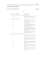
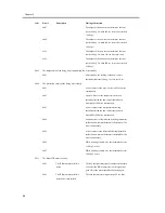
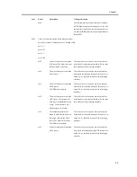
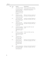
Page 43: ...Contents Contents 3 1 Error Code Details 3 1 3 1 1 Error Code Details Table 3 1 ...
Page 44: ......
Page 63: ...Chapter 4 User Mode Items ...
Page 64: ......
Page 66: ......
Page 79: ...Chapter 5 Service Mode ...
Page 80: ......
Page 82: ......
Page 121: ...Chapter 6 Outline of Components ...
Page 122: ......
Page 124: ......
Page 134: ...Chapter 6 6 10 F 6 6 PLG1 ELCB1 SP1 H4 H3 H2 H1 H1 H2 LA1 ...
Page 138: ...Chapter 6 6 14 ...
Page 139: ...Chapter 7 System Construction ...
Page 140: ......
Page 142: ......
Page 157: ...Chapter 8 Upgrading ...
Page 158: ......
Page 160: ......
Page 168: ...Chapter 8 8 8 ...
Page 169: ...Dec 3 2004 ...
Page 170: ......


