


Chapter 2
2-10
Use it to adjust the timing at which the registration
roller clutch goes ON.
COPIER>ADJUST>FEED-ADJ>ADJ-REFE
Use it to adjust the horizontal registration for re-
pickup.
COPIER>ADJUST>CST-ADJ>MF-A4R
Use it to adjust the paper width basic value for the
manual feed tray.
COPIER>ADJUST>CST-ADJ>MF-A6R
Use it to adjust the paper width basic value for the
manual feed tray.
COPIER>ADJUST>CST-ADJ>MF-A4
Use it to adjust the paper width basic value for the
manual feed tray.
3) Turn off and then on the main power switch.
4) Make the following selections in service mode:
COPIER>FUNCTION>LASER>L-ADJ-0.
5) Press the OK key. (The machine starts auto
adjustment and will indicate 'END' at its end.)
2.6.3
When Replacing the
Main Controller PCB
(main)
0000-5364
Be sure to use the image memory (SDRAM) [1] PCB
and the boot ROM [2] from the old PCB on the new
main controller PCB (main).
F-2-21
F-2-22
2.6.4
When Replacing the
Main Controller PCB
(sub)
0006-3263
Be sure to use the SRAM PCB [1] from the old PCB
on the new main controller PCB (sub) [2].
F-2-23
2.6.5
When Replacing the
SRAM PCB
0000-5365
When the SRAM PCB is replaced, all data in its
memory will be lost (file-related, user mode-related,
service mode-related, history-related files). There will
be no error operation, and initialization will take place
automatically.
If you pull out the SRAM PCB from machine B and
mount it to machine A, the PCB will be initialized and
be rendered useless for machine A or B. Take full
care.
Summary of Contents for iR C3200 Series
Page 1: ...Dec 3 2004 Portable Manual iR C3200 Series iR C3220N PRT ...
Page 2: ......
Page 6: ......
Page 10: ......
Page 11: ...Chapter 1 Maintenance and Inspection ...
Page 12: ......
Page 14: ......
Page 22: ...Chapter 1 1 8 ...
Page 23: ...Chapter 2 Standards and Adjustments ...
Page 24: ......
Page 26: ......
Page 40: ...Chapter 2 2 14 ...
Page 41: ...Chapter 3 Error Code ...
Page 42: ......
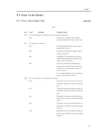
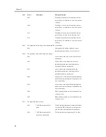
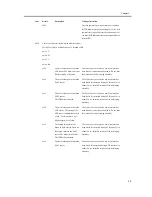
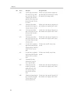
Page 43: ...Contents Contents 3 1 Error Code Details 3 1 3 1 1 Error Code Details Table 3 1 ...
Page 44: ......
Page 63: ...Chapter 4 User Mode Items ...
Page 64: ......
Page 66: ......
Page 79: ...Chapter 5 Service Mode ...
Page 80: ......
Page 82: ......
Page 121: ...Chapter 6 Outline of Components ...
Page 122: ......
Page 124: ......
Page 134: ...Chapter 6 6 10 F 6 6 PLG1 ELCB1 SP1 H4 H3 H2 H1 H1 H2 LA1 ...
Page 138: ...Chapter 6 6 14 ...
Page 139: ...Chapter 7 System Construction ...
Page 140: ......
Page 142: ......
Page 157: ...Chapter 8 Upgrading ...
Page 158: ......
Page 160: ......
Page 168: ...Chapter 8 8 8 ...
Page 169: ...Dec 3 2004 ...
Page 170: ......


