COPYRIGHT © 2005 CANON ELECTRONICS INC. CANON DR-2580C FIRST EDITION APR. 2005
3-13
CHAPTER 3 DISASSEMBLY/ASSEMBLY
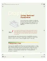
2. Retard Roller Shaft Unit
1) Remove the retard roller.
2) Remove the right cover, left cover and
PCB unit.
3) Insert thin and flat head tools into the 2
fitting parts
{
1 and remove the roller
cover
{
2 .
Figure 3-309
4) Insert thin and flat head tools into the
small hole
{
2 of the 2 C shaped collars
{
1
and pull then out.
Note:
Slightly press the C shaped collars when
pulling it out to prevent it from being
blown away.
Figure 3-310
5) Push and rotate the right and left shafts
{
1
to insert their edges into the inside of the
frame.
Figure 3-311
6) Rotate the retard roller shaft unit
{
1 and
unhook the left and right fitting parts
{
2 .
Figure 3-312
* Notes on assembly
Make sure if the retard roller smoothly
rotates after the completion of assembly.
Summary of Contents for imageFORMULA DR-2580C
Page 4: ......
Page 8: ......
Page 26: ......
Page 66: ......
Page 92: ......
Page 94: ......
Page 102: ......
Page 104: ......
Page 124: ......
Page 126: ......
Page 128: ......
Page 130: ...0305TG ...
Page 139: ...COPYRIGHT 2005 CANON ELECTRONICS INC CANON DR 2580C FIRST EDTION APR 2005 ...
Page 158: ...COPYRIGHT 2005 CANON ELECTRONICS INC CANON DR 2580C FIRST EDTION APR 2005 ...
Page 160: ...vii 0405TG ...