background image


COPYRIGHT © 2005 CANON ELECTRONICS INC.      CANON DR-2580C FIRST EDITION APR. 2005


4-3


CHAPTER 4  INSTALLATION & MAINTENANCE

3. Roller 

Installation 

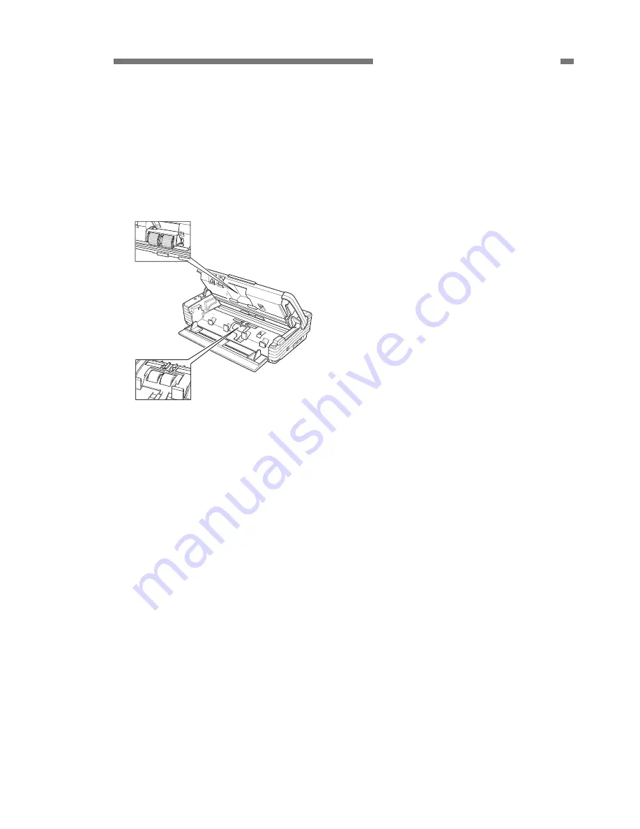
Install the supplied “roller unit” and “retard 

roller” on the main body. For the installation 
method, refer to the user manual or 
“CHAPTER 1 INTRODUCTION, VI. User 
Maintenance” of this manual. 

Roller unit

Retard roller


Figure 4-106 

4.  Connection to the computer 

1)  Check whether the computer has an I/F 

card and install one if necessary. 

2)  Connect an USB interface cable.  
3)  Connect the supplied AC adapter and 

power cord. Be sure to use the supplied 
power cord. 

4)  Switch this machine ON and then turn the 

computer ON.  

5)  Let the computer to recognize this ma-

chine (scanner). 

6)  Install software (drivers and applications) 

necessary for the computer. 

7)  Restart the computer as required. 

 
5. Operation 

Check 

1) Install the supplied document guide 

adapters as required. 

2) Set 

documents. 

3)  Run the application software according to 

the operation procedure. 

4)  Check operation results.  


Summary of Contents for imageFORMULA DR-2580C

Page 1: ...COPYRIGHT 2005 CANON ELECTRONICS INC CANON DR 2580C FIRST EDITION APR 2005 FIRST EDITION APR 2005 MY8 13A5 000 ...

Page 2: ...COPYRIGHT 2005 CANON ELECTRONICS INC Use of this manual should be strictly supervised to avoid disclosure of confidential information ...

Page 3: ...ction Chapter 3 Disassembly and reassembly Disassembly method reassembly method Chapter 4 Installation and maintenance Installation method maintenance method Chapter 5 Troubleshooting Service modes and troubleshooting Appendix General circuit diagrams etc Information in this manual is subject to change Notification of such changes will be given in Service Information Bulletins Thoroughly read the ...

Page 4: ......

Page 5: ...USER OPERATION 1 10 VI USER MAINTENANCE 1 12 CHAPTER 2 FUNCTIONS OPERATION I OUTLINE 2 1 II READING SYSTEM 2 5 III FEED SYSTEM 2 8 IV CONTROL SYSTEM 2 11 V IMAGE PROCESSING 2 14 VI POWER SUPPLY 2 30 VII FLATBED UNIT 2 31 VIII ELECTRICAL PARTS LAYOUT 2 35 IX PARTS LAYOUT OF EACH PCB 2 37 CHAPTER 3 DISASSEMBLY REASSEMBLY I EXTERNAL COVERS 3 1 II UPPER UNIT 3 4 III LOWER UNIT 3 10 IV FLATBED 3 21 ...

Page 6: ...I INSTALLATION 4 1 II PERIODICALLY REPLACED PARTS 4 5 III CONSUMABLE PARTS 4 6 IV LIST OF PERIODIC MAINTENANCE ITEMS 4 7 CHAPTER 5 TROUBLESHOOTING I ERROR DISPLAY 5 1 II SERVICE MODE 5 2 III IMAGE TROUBLESHOOTING 5 13 IV OPERATION TROUBLESHOOTING 5 16 V AFTER REPLACING PARTS 5 19 APPENDIX I GENERAL DIAGRAM A 1 ...

Page 7: ...RAL DESCRIPTION COPYRIGHT 2005 CANON ELECTRONICS INC CANON DR 2580C FIRST EDITION APR 2005 I FEATURES 1 1 II SPECIFICATIONS 1 2 III PRECAUTIONS 1 6 IV NAME OF PARTS 1 7 V USER OPERATION 1 10 VI USER MAINTENANCE 1 12 ...

Page 8: ......

Page 9: ...lex 13 ppm Duplex 26 ipm 200 dpi A4 size 3 Dual path mechanism U turn Straight path Straight path is provided for thicker documents and cards 4 Flatbed scanner for option It can be attached and detached by users 5 Installation and replacing of consumable parts by users with flatbed Figure 1 101 Windows is a trademark of Microsoft Corporation in the U S and other countries Other company names and p...

Page 10: ...0 to 80 RH No condensation allowed 5 Noise 1 Sound power level In standby mode 40 dB or less In operating mode 66 dB or less 2 Sound pressure level Bystanders reference In operating mode 57 dB or less 6 Dimensions Tray closed 302 W 171 D 81 H mm 7 Weight Approx 1 9 kg 8 Output interface 1 USB2 0 Hi speed 2 Flatbed s interface 9 Expected product life in house information One of the following two it...

Page 11: ...s permitted 4 Document requirements 1 Pressure sensitive paper Can be fed with limitation of direc tion 2 Carbon backed paper Cannot be fed 3 Perforated paper for binder Can be fed with limitation of holes 4 Curled paper Can be fed only if curl is 5 mm or less 5 Creased paper Can be fed but crease must be straightened before being fed U turn path Straight path 1 Pickup 5 mm or less including curls...

Page 12: ...t only 6 Reading size 1 Typical A4 A5 A5 R A6 A6 R B5 B6 B6 R LGL LTR 2 Auto size detection 3 Maximum size 216 355 mm 4 User setting 7 Output mode 1 Binary Black White Error diffusion Advanced text en hancement 2 Grayscale 8 bit 3 Color 24 bit 8 Output resolution 100 100 dpi 150 150 dpi 200 200 dpi 240 240 dpi 300 300 dpi 400 400 dpi 600 600 dpi A4 size documents Mode Resolution Single Double 200 ...

Page 13: ...xt orientation 9 Counter Total fed counts memorize in scanner 10 Operation buttons job buttons 3 buttons available registering the functions Table 1 204 5 Flatbed Unit option No Item Specifications 1 Type Desktop type flatbed scanner No operation without main body DR 2580C 2 Dimensions tray closed Flatbed itself 315 W 545 D 82 5 H mm With DR 2580C 315 W 557 D 155 H mm 3 Weight Approx 3 8 kg with D...

Page 14: ...plug the power cord immediately Also do not insert your fingers in the feed section while feeding documents 2 Prohibition of Modify Do not change nor modify this machine If this has been carried out its use may be forcibly discontinued on site If this machine s specifications shall be changed or the machine shall be disassem bled and reassembled follow the instructions described in this manual or ...

Page 15: ... EDITION APR 2005 1 7 CHAPTER 1 GENERAL DESCRIPTION IV NAME OF PARTS 1 Front Pickup selection lever Job buttons Eject tray upper unit Eject tray extension 2 Pickup tray Document guide Eject tray extension Power indicator OPEN knob Document guide Figure 1 401 ...

Page 16: ... EDITION APR 2005 CHAPTER 1 GENERAL DESCRIPTION 2 Rear Kensington slot Eject selection lever Up Straight path Down U turn path Job label location Eject opening Figure 1 402 3 Side interface USB connector Power switch Option connector Power connector Figure 1 403 ...

Page 17: ...T EDITION APR 2005 1 9 CHAPTER 1 GENERAL DESCRIPTION 4 Flatbed unit option Pressure board black Flatbed platen glass Interface cable Auxiliary paper support plate Scanning unit slide lock Flatbed cover DR 2580C locking hook DR 2580C locking hook Figure 1 404 ...

Page 18: ...d by the user If they are performed by a service technician refer to the user manual CHAPTER 4 INSTALLATION MAINTENANCE in this manual provides an overview However the next section USER MAINTENACE shows how to install the roller unit and retard roller 2 Operation Screen Basic operation screens if CapturePerfect 3 0 is used are shown for reference Cap turePerfect 3 0 uses an ISIS driver 1 Main scre...

Page 19: ...the eject tray and then close the eject tray extension Figure 1 505 2 Open the rear cover by pressing the both sides Figure 1 506 3 Push the OPEN knob from both sides and open the upper unit slowly Figure 1 507 4 Remove the jammed document carefully Figure 1 508 5 Close the upper unit slowly Figure 1 509 6 Close the rear cover by pressing the both sides ...

Page 20: ...4 Reading glass 5 Shading plates 2 Roller Replacement The roller unit and retard rollers are con sumables They should be replaced when 100 000 sheets are fed as a guide They are replaced by the user The roller unit has the pickup roller and retard roller a Replacement message When the number of sheets fed exceeds 100 000 a roller replacement message is displayed on the display when the computer is...

Page 21: ...ra to display the Properties screen for this machine and click the Reset button for the counter Figure 1 602 b Roller unit Removal 1 Push the OPEN knob from both sides and open the upper unit slowly Figure 1 603 2 Raise the roller locking lever Figure 1 604 3 Hold the roller unit with your fingers and slide the locking lever to the right Figure 1 605 4 Detach the right side of the roller unit firs...

Page 22: ...ver and slide it to the right 3 Set the roller unit on the shaft of the main body Figure 1 607 4 Insert the projection on the roller unit into the groove in the main body and lift the roller unit Figure 1 608 5 Slide the roller locking lever to the left and then push it backward to secure the roller unit Figure 1 609 c Retard roller Removal 1 Push the OPEN knob from both sides and open the upper u...

Page 23: ... the right and remove it Figure 1 613 Reinstallation 1 Push the OPEN knob from both sides and open the upper unit 2 Remove the roller cover 3 Raise the roller locking lever and slide it to the right 4 Align the notch in the retard roller with the shaft of the main body and set it Figure 1 614 5 Slide the roller locking lever to the left fit it into the hole in the retard roller and push the lever ...

Page 24: ...1 16 COPYRIGHT 2005 CANON ELECTRONICS INC CANON DR 2580C FIRST EDITION APR 2005 CHAPTER 1 GENERAL DESCRIPTION 6 Install the roller cover Figure 1 616 ...

Page 25: ...NICS INC CANON DR 2580C FIRST EDITION APR 2005 I OUTLINE 2 1 II READING SYSTEM 2 5 III FEED SYSTEM 2 8 IV CONTROL SYSTEM 2 11 V IMAGE PROCESSING 2 14 VI POWER SUPPLY 2 30 VII FLATBED UNIT 2 31 VIII ELECTRICAL PARTS LAYOUT 2 35 IX PARTS LAYOUT OF EACH PCB 2 37 ...

Page 26: ......

Page 27: ...from image sensors 2 Feed System This system performs from document pickup to document ejection 3 Control System This system is comprised of an image processing section and a feed control section The image processing section controls the reading system processes the read im age data and outputs it to the computer However the image data processing is also performed by the computer The feed control ...

Page 28: ...ve This machine has a pickup motor M1 and a carry motor M2 for feeding the docu ment These motors drive the stopper and the reading unit Retard roller Eject roller 1 Carry roller Eject roller 2 Carry motor Pickup motor Control PCB Switch PCB Registration roller Pickup roller Feed roller Torque limiter M1 M2 Figure 2 102 ...

Page 29: ... 3 Electrical Circuits Figure 2 103 shows an overview of the electrical circuits block diagram of this ma chine Control PCB Document board sensor PCB I F Connector Motor Sensor Switch PCB Reading unit back Flatbed unit Option AC adapter Sensor Power LED Switch CIS PCB CIS PCB Reading unit front Figure 2 103 ...

Page 30: ...s the timing chart when you separately feed two sheets of document without temporarily suspending the machine Document board sensor Carry motor Pickup motor Pre registrarion sensor Registration sensor Document reading Start End Reading speed Reading speed 2nd document 1st document Reversal stopper Closed reading unit lower to fornt Figure 2 104 ...

Page 31: ...ding system The reading unit upper reads the front side of the documents and the reading unit lower reads the back side of the documents This configuration enables the unit to read both the front and back sides of a document using a single scan The image data read are sent to the image processing section of the control PCB Reading unit upper Reading unit lower Document Figure 2 201 ...

Page 32: ...ive picture elements is 5104 Two sets of three basic color LEDs red green and blue RGB are mounted in the CIS unit In the binary or grayscale modes image data are read with composite light generated by lighting the RGB LEDs simul taneously In the color mode the LED is suc cessively lit and reads image data with each color As documents are being fed at regular speed while image data are read the re...

Page 33: ...ut 2 mm to the document pickup side Figure 2 204 describes the structural drawing of that part If the carry motor is ro tated opposite to the feed direction the me chanical clutch which is installed on the shaft of the eject roller 1 rotates At this point in time the coupling plate starts rotating by the head of the coil spring and the reading unit moves horizontally When such motor normally rotat...

Page 34: ...sectional diagram of the feed system 1 Pickup roller 2 Feed roller 3 Retard roller 4 Follower roller 5 Registration roller 6 Follower roller 7 Eject roller 1 8 Carry roller 9 Eject roller 2 10 Reading unit upper 11 Reading unit lower 12 Stopper 13 Flapper Figure 2 301 Note The pickup roller and the feed roller make up a single unit called a roller unit ...

Page 35: ...e roller begins to rotate in the same direction As shown in Figure 2 302 a when over lapped documents enter into the clear ance between the feed roller and the re tard roller the document in contact with the feed roller is fed in the feed direction and the retard roller does not rotate so that the document in contact with the re tard roller is not pushed in As shown in Figure 2 302 b once a single...

Page 36: ...the document is detected before the motor drives the specified length about 40 mm 4 Non removable jam When the registration sensors detect the presence of the document when the power is ON or after the upper unit opens and closes 5 Double feed detection This machine checks the double feed by detecting the document length by the registration sensors The detection process is the same as the above th...

Page 37: ...Figure 2 401 shows the block diagram of the control PCB I F for FB Image memory section SDRAM 8MB I F for front sensor Data controller Regain USB control section USB I F Analog processor I F for back sensor CPU BUS CPU memory section CPU Main body control section Motor control section FLASH_ROM SRAM EEPROM FB motor I F Detection sensor section Key switch section Power control section Figure 2 401 ...

Page 38: ...log processor Offset adjustment Gain adjustment A D conversion Data controller LED light control Resolution conversion 12bit 8bit Computer Flatbed Option Shading correction 1 dimensional gamma correction Binary Color Edge emphasis Binarizing Grayscale Data after shading correction USB interface Data after image processing Other processing Size detection Black border removal Binder hole removal Oth...

Page 39: ...A D con version Analog signals are converted into 12bit digital signals in the analog processor Then the image data is transferred to the data controller and the resolution is converted from 12 bits to 8 bits After that the image data is output to the computer through an USB interface All the image processing carried out in this machine are described above Other image processing are carried out in...

Page 40: ... Gain adjustment Gain adjustment is carried out on analog signals for the whole image sensor White correction is adjusted so that the maxi mum output value of the overall white level matches the specified value Note Offset and gain adjustment are used to perform A D conversion properly 3 A D conversion This processing converts analog signals into digital signals The analog processor unique to this...

Page 41: ...nversion by averaging is sometimes called smoothing Averaging method conversion enables the data to be smoothly transformed much better than that by thinning out method resulting in reducing the oc currence of Moire patterns Averaging is especially useful for low resolution photographs The data are averaged according to the resolution applied when the basic data of each picture element are con ver...

Page 42: ...hree times the speed used for 300 dpi If the timing for reading the data from the image sensor is the same the resolution in the sub scanning direction can be converted by changing the feeding speed Figure 2 502 However the feeding speed is limited depending on the specifications of carry motor If the feeding speed can not be increased the read timing in terval is widened Figure 2 503 Feeding spee...

Page 43: ...in other words when a black image is read in tense black is set as a target value For white correction value readout of stan dard shading plate is set as a target value pure white The data of each element which have been converted into digital signals are compensated in accordance with the corresponding values After A D conversion LEDS turned off Black correction value Figure 2 504 White document ...

Page 44: ...e Help function The conversion tables below are for fun damental items and may be different from actual items a Brightness Adjustment This adjusts the overall brightness of the scanned image The image brightness increases as the setting value becomes larger and decreases as the value becomes smaller For brightness adjustment in black and white mode refer to the Binarizing section Y0 YH White 255 A...

Page 45: ...an brightness and contrast adjustments is required It is possible for the user to use a custom conversion table for converting the gamma curve to the document image data In this case the bright ness and contrast adjustments be come invalid and the unique gamma curve is given priority YH White 255 White 255 Black 0 Y0 YL X0 After conversion Before conversion Figure 2 508 ...

Page 46: ...ng is performed by compar ing the data in the conversion table pro vided for performing edge emphasis with the target picture element data a Figure 2 510 The stages in edge emphasis can be changed by changing the conversion table and reproduction ratio B of the conver sion table For example if the target picture element data is increased fourfold and the other four points multiplied by 1 the overa...

Page 47: ...rightness must be cut off at a certain level so that anything above that level is judged as white and anything below as black This is called simple binarizing This is useful for text documents Simple bi narizing for this machine is called Black and White mode The level at which picture elements are to be divided into white or black is called the slice level The image brightness is adjusted by chan...

Page 48: ... next picture element to be processed First when processing the first low of Line 1 since the data 12 is larger than the slice level 8 the output data be comes 15 and the resultant error becomes 3 12 15 Figure 2 512 12 9 6 3 1 9 13 Input data 15 Output data 12 8 15 3 Error 3 12 15 Output Input First row of line 1 Figure 2 512 Next when processing the second row of Line 1 since the error is diffuse...

Page 49: ... 15 0 15 15 15 0 0 0 0 0 15 15 15 0 15 15 15 0 15 15 0 0 0 0 0 Input data Output data Figure 2 514 Figure 2 515 shows a comparison of binarizing with error diffusion proc essing and binarizing without error diffusion processing simple binariz ing The brightness adjustment for error diffusion is done by using the data conversion table The slice level is al ways set at median 12 10 9 11 12 9 13 12 8...

Page 50: ...image in Figure 2 516 a histogram for each block is calculated and the optimum slice level is determined to binarize the picture ele ments Slice level Brightness level Black White Frequency of appearance Figure 2 516 6 Automatic Size Detection In case that the automatic size detection mode is selected an image data with the maximum width and the length detected by the registration sensors in the f...

Page 51: ... document is dark or brightness level is not appropriately set this function may not successfully work This may also happen when the skew correction or black frame removal described later is performed 7 Skew Correction Deskew If the skew correction is selected the size of document read is broadened by 10 mm compared with the user specified size The skew is detected based on the data read to compen...

Page 52: ...mage data and the outside of the frame is converted into the white data Figure 2 520 The conventional black border removal may vanish the letters if there are some letters on the edge of document and the document is skewed to much This ma chine extracts the outer shape of docu ment without dent after extracting the frame Thus no letters vanish Figure 2 521 ABC ABC Specifed size Figure 2 520 Outer ...

Page 53: ...es by using the front and back sides of an image Figure 2 522 The procedures and principle are de scribed below Note If the scan area is specified and the optional flatbed unit is attached to this machine the processing is different from this processing to perform the only sim plex scanning i The front and back sides of document are read Figure 2 523 ii The image of the back side is reversed Figur...

Page 54: ...leted as well In this case the low pass filter processing should be done to handle and delete small objects v The shapes such as area circumfer ence and center of balance of the binder holes of the hole pattern front and back side images are compared If they are the same those black objects are determined as binder holes And then they are removed from the front image vi In case that both sides of ...

Page 55: ...ts whose area is 10 mm2 or less are excluded Degree of circularity area 4π circumference 2 10 Blank Skip Judgment as to whether or not to record a document is determined by comparing the actual number of picture elements of the document with the user preset percent age 0 to 20 of number of black pic ture elements However the margin of an image data 10 of lengths of each side edge is ex cluded Thus...

Page 56: ...ors respectively The power for the optional flatbed unit is supplied by this machine The AC adapter has the overload protection function to automatically block the power output in the event of a failure such as short circuit on the load side of the AC adapter This machine will shift into the power saving mode if such states as no document feeding and no USB interface communication continue In the ...

Page 57: ...ad images Table 2 701 includes the key specifica tions of the flatbed unit No Item Specifications 1 Type Desktop type flatbed scanner No operation without main body DR 2580C 2 Dimensions tray closed Flatbed itself 315 W 545 D 82 5 H mm With DR 2580C 315 W 557 D 155 H mm 3 Weight Approx 3 8 kg with DR 2580C Approx 5 7 kg 4 Type of sensor CCD 5340 picture elements 4 lines RGB Grayscale 5 Effective p...

Page 58: ...ch consists of the CCD PCB with the CCD sensor 4 mirrors lens and xenon lamp as a light source is called optical unit Since this unit is adjusted before the shipment from a plant do not disassemble the unit except for the lamp in the field The images of a document are reduced by the optical unit And then the 600dpi im age data with 5104 effective picture ele ments length 210 mm are output from the...

Page 59: ...ead in the sub scanning direction by moving the op tical unit horizontally A timing belt is fixed to the optical unit The rotations of the stepping motors run the timing belt to move the optical unit A shaft is installed as a guide for the unit move ment Motor Timing belt Optical unit Document board glass Guide Shaft Stopper Shaft Figure 2 703 ...

Page 60: ...tical CCD PCB those data are output to the main body of DR 2580C Figures 2 704 and 2 705 describe the electric circuit block diagram and image processing block diagram respectively DR 2580C Control PCB CCD PCB Optical unit Lamp Inverter DR 2580C Switch PCB Connector PCB Connector PCB Motor Figure 2 704 CCD Analog processor Offset adjustment Gain adjustment A D conversion 12bit Data controller Lamp...

Page 61: ...L PARTS LAYOUT 1 Main Body M2 M1 PS2 PS5 M2 M1 PS3 PS4 PS1 PS7 PS6 Figure 2 801 Category Name Symbol Power supply sensor PS1 Rear cover sensor PS2 Upper opening sensor PS3 Document board sensor PS4 Shading sensor PS5 Pre registration sensor PS6 Sensor Registration sensor PS7 Pickup motor M1 Motor Carry motor M2 Table 2 801 ...

Page 62: ...LECTRONICS INC CANON DR 2580C FIRST EDITION APR 2005 CHAPTER 2 FUNCTION OPERATION 2 Flatbed M3 PS8 FL1 Figure 2 802 Category Name Symbol Sensor Optical unit sensor PS8 Motor Optical motor M3 Lamp Light source lamp FL1 Table 2 802 ...

Page 63: ... not be procured in the field 1 Controller PCB J102 J4 J701 J501 J502 J2000 LED101 LED501 J1001 J1000 Figure 2 901 Connector Description J4 9P Flatbed J102 2P AC adapter 16 VDC J501 16P CIS PCB front J502 16P CIS PCB back J701 5P USB I F J1000 19P Switch PCB J1001 4P Document board PCB J2000 7P Ultrasonic sensor PCB Table 2 901 LED Description LED101 Blinking CPU normal opera tion LED501 Lighting ...

Page 64: ...APTER 2 FUNCTION OPERATION 2 DC Control PCB SW202 SW201 SW200 J200 J202 J201 LED200 Figure 2 902 Connector Description J200 19P Control PCB J201 4P Pickup motor J202 4P Carry motor Table 2 903 LED Description LED200 Lighting Normal Blinking Scanner abnormal jams and so on Table 2 904 ...

Page 65: ...CHAPTER 3 DISASSEMBLY REASSEMBLY COPYRIGHT 2005 CANON ELECTRONICS INC CANON DR2580C FIRST EDITION APR 2005 I EXTERNAL COVERS 3 1 II UPPER UNIT 3 4 III LOWER UNIT 3 10 IV FLATBED 3 21 ...

Page 66: ......

Page 67: ...or E rings Do not deform such parts too much while working because they would be dam aged However do not leave a gap between the parts when installing them 3 Prepare a thin and flat head tool such as precision driver because it is nec essary to unhook some fitting parts I EXTERNAL COVERS 1 Rear Cover 1 Fully open the rear cover 2 Bend the left or right arm 1 unhook the fitting parts and remove the...

Page 68: ...3 also comes off Figure 3 102 Notes on assembly Do not pinch the cable In case that the power switching lever comes off be sure to put it back 3 Left Cover 1 Remove the rear cover and fully open the pickup tray and upper unit 2 Unhook the 4 fitting parts 1 one of them on the back side and remove the left cover 2 At this time the pickup tray 3 also comes off Figure 3 103 Notes on assembly Set the r...

Page 69: ... 5 Upper Cover 1 Remove the right cover 2 After unhooking the 6 fitting parts 1 close the upper unit and remove the upper cover assembly 2 Note The arm 3 of the left and right reading units would come off after removing the upper cover assembly Figure 3 104 3 After opening the eject tray extension assembly 1 rotate it and remove the upper cover 2 Figure 3 105 Notes on assembly Do not pinch the cab...

Page 70: ...ble for the reading unit Figure 3 201 3 After further opening the upper unit slide it to the left unhook the right fitting parts 1 and remove the upper unit Note Do not pull the upper unit too hard be cause the cable 2 is connected to it Figure 3 202 4 After unhooking the fitting parts 2 which are put on the base of the reading unit arms 1 rotate the arms and unhook the fitting parts 3 which are p...

Page 71: ...ft and coil spring would jump out when removing them Do not mix up the coil spring for the follower roller ahead with the one for the follower roller behind because they are different The coil spring for the fol lower roller behind is white Figure 3 204 6 Remove the reading unit 1 and discon nect the cable 2 which is connected to its back side Note In case that the cable which is con nected to the...

Page 72: ...aft and coil spring would jump out when removing them The coil spring for the follower roller ahead is metallic color Figure 3 207 3 Follower Roller Behind 1 Fully open the upper unit Note In case that there is not enough room to disassemble the follower roller behind remove the right cover left cover and upper cover assembly to further open the upper unit 2 Rotate the roller shaft 1 to bring the ...

Page 73: ...he roller unit 2 Remove the right cover and upper cover assembly 3 Remove the open close knob 1 Figure 3 209 4 Unhook the fitting parts 1 with a thin and flat head tool and remove the drive gear 2 Figure 3 210 5 Unhook the fitting parts 1 and rotate the bearing 2 90 degrees After that slide the roller drive shaft 3 to remove it Figure 3 211 ...

Page 74: ...sembly and fully open the upper unit 2 Refer to the procedure for Upper Unit to remove the 4 arms 1 of the reading unit and follower roller ahead 2 Figure 3 212 3 Remove the reading unit 1 and discon nect the cable 2 which is connected to its back side Figure 3 213 Notes on assembly Install the reading unit so that the coil spring on its back side can contact the grounding plate ...

Page 75: ...rom getting into the CIS unit Figure 3 215 Notes on assembly 1 Remove scraps of paper or other foreign particles out of the CIS unit with a tool such as blower Install it after cleaning its inside including the glass which is put on the reading holder And make sure that the coil spring is put in the cover Notes on assembly 2 Do not stain or damage the shading plate installed on the reading holder ...

Page 76: ...rs 2 Figure 3 301 3 Insert a thin and flat head tool into the hole 1 on the back side to remove the plate 2 Then unhook the 2 fitting parts 3 and open the plate to the direction of the arrow Be aware that the cable is con nected to the inside of the unit Figure 3 302 4 Disconnect the 3 cables 1 which are connected to the PCB unit and remove the PCB unit 2 Note Be careful not to lose the sensor cov...

Page 77: ...e reinforcing plate for the contacts of the cable 1 which is con nected to the lower unit is blue and this cable should be connected to the con nector J502 The cable 2 which is con nected to the upper unit is aluminum shielded and it should be connected to the connector J501 Figure 3 304 Notes on assembly 2 Do not pinch the cables Put the 2 cables 1 which are connected to the upper unit in the 2 c...

Page 78: ...Roller Shaft Unit Figure 3 306 4 Remove the motor drive unit For more details refer to the section Drive Unit 5 Remove the gear 1 clutch gear 2 and 2 ball bearings 3 Note Unhook the fitting parts mounted on the edge of the gear to pull the gear out Figure 3 307 6 Pull the leaf spring 1 out of the fitting parts And then pull the sensor lever 2 out of the fitting parts Finally remove the registratio...

Page 79: ...4 Insert thin and flat head tools into the small hole 2 of the 2 C shaped collars 1 and pull then out Note Slightly press the C shaped collars when pulling it out to prevent it from being blown away Figure 3 310 5 Push and rotate the right and left shafts 1 to insert their edges into the inside of the frame Figure 3 311 6 Rotate the retard roller shaft unit 1 and unhook the left and right fitting ...

Page 80: ...tting parts 3 and remove the moving arm And also remove the edge 4 of the spring clutch Figure 3 313 3 Insert thin and flat head tools into the 2 fitting parts 1 and remove the roller cover 2 Figure 3 314 4 Remove the gear 1 right and left bearing stoppers 2 and 3 Remove the eject roller 1 4 And then remove the me chanical clutch 5 out of the eject roller Note Unhook the fitting parts mounted on t...

Page 81: ...ote Unhook the fitting parts mounted on the edge of the gear to pull the gear out Unhook the fitting parts to remove the bearing stopper 3 Figure 3 316 5 Carry Roller 1 Remove the left cover Fully open the rear cover 2 Remove the gear 1 right and left bearing stoppers 2 and 3 And remove the carry roller 4 Note Unhook the fitting parts mounted on the edge of the gear to pull the gear out Pull the b...

Page 82: ...ght to remove it Note The left side connector in the figure is for the carry motor Figure 3 318 Notes on assembly Reeve the timing belt on the gear of the carry motor If it is hard to do it remove the motor mounting plate For more details refer to the section Drive Unit 2 Pickup Motor 1 Remove the left cover 2 Remove the connector 1 and 2 screws 2 And remove the carry motor 3 Note The right side c...

Page 83: ...Unit 1 Remove the right cover left cover and PCB unit 2 Remove the 2 screws 1 And remove the drive unit 2 Note The gear or something would drop when removing the drive unit Figure 3 320 Notes on assembly Before installing the drive unit install the gear grounding plate and lever in the appropriate positions Figure 3 321 ...

Page 84: ...o remove it Note The cable is connected to the right back side Figure 3 322 3 Disconnect the cable 1 and remove the reading unit 2 Figure 3 323 2 Reading Holder with Glass 1 Remove the reading unit 2 Unhook the 8 fitting parts 1 with a thin and flat head tool and remove the cover 2 Note Since the fitting part is bent easily un hook it carefully Figure 3 324 3 Draw the CIS unit 2 out of the reading...

Page 85: ...its inside including the glass which is put on the reading holder Notes on assembly 2 Do not stain or damage the shading plate installed on the reading holder If it is stained clean it and if it is damaged re place the reading holder Notes on assembly 3 The reading unit cover and CIS unit are the same as those for the upper unit On the other hand their reading holders are different in shape And no...

Page 86: ...n trol PCB cannot be removed Figure 3 326 3 Remove the 8 screws 1 and remove the control PCB 2 Note The screws on the USB connector are M3 and the others are M2 5 Figure 3 327 2 Switch PCB 1 Remove the PCB unit 2 Remove the connector 1 and spring 2 And remove the 2 screws 3 and remove the switch PCB 4 Note The connector which should be re moved is mounted on the switch PCB as indicated in the figu...

Page 87: ...move the dust if there is inside the unit 2 Flatbed Cover Assembly 1 Fully open the flatbed cover 2 Bend the stopper 1 insert a tool into the gap of the shaft 2 and slide the flatbed cover assembly 3 until it is removed Figure 3 402 Notes on part replacement A black pressure board needs to be put on the position on which the document board glass is actually mounted Thus when replacing a part prepa...

Page 88: ...Adhesive tape Black pressure board Upper cover Sponge Black sheet Origin point Figure 3 403 3 Slowly close the flatbed cover so that the black pressure board does not shift And gently press the cover to stick the black pressure board to it 3 Eject Tray 1 Slightly lift the edge of the eject tray 1 put it on the outer frame to remove it Figure 3 404 4 Lock Board for Optical Unit 1 Remove the upper u...

Page 89: ... 2005 3 23 CHAPTER 3 DISASSEMBLY ASSEMBLY 5 Hook for Main Body 1 Remove the upper unit 2 Bend the 2 stoppers 1 mounted on the back side of the upper unit and remove the hook 2 Note The same procedure applies to the disassemblies of both right and left hooks Figure 3 406 ...

Page 90: ...disconnect the cable 2 from the PCB and pull the main shaft 3 out of the optical unit 4 Note When disconnecting the cable from the connectors press those connectors by hand to prevent the PCB from being damaged Figure 3 407 3 Remove the timing belt 1 and cable guide 2 out of the optical unit 3 Figure 3 408 Note Do not remove the cover of the optical unit Do not touch the glass tube of the lamp Not...

Page 91: ...e high voltage is applied to the lamp Figure 3 410 3 Motor Unit 1 Remove the upper unit 2 Remove the contact assembly 3 Remove the 2 screws 1 and remove the motor unit 2 Figure 3 411 Notes on assembly Reeve the belt for the optical unit on the pulley Tension adjustment for belt If the tension of the belt for the optical unit needs to be adjusted use the tension adjustment plate which is mounted on...

Page 92: ......

Page 93: ...ALLATION MAINTENANCE COPYRIGHT 2005 CANON ELECTRONICS INC CANON DR 2580C FIRST EDITION APR 2005 I INSTALLATION 4 1 II PERIODICALLY REPLACED PARTS 4 5 III CONSUMABLE PARTS 4 6 IV LIST OF PERIODIC MAINTENANCE ITEMS 4 7 ...

Page 94: ......

Page 95: ... indicated on the box Quick reference guide Power cord Startup manual AC adapter DR 2580C setup disc USB interface cable Adobe Acrobat setup disc DR 2580C main body Document guide adapter Warranty card only for 100 V and 120 V models Job labels Roller unit Retard roller Application kit only for 100 V model Figure 4 101 The DR 2580C setup disk is inserted in the startup manual Retain the outer pack...

Page 96: ...ve it while holding the eject tray extension by hand 2 Push both sides of the rear cover open it backward and remove the protection sheet Rear cover Figure 4 103 3 Push both sides of the rear cover and close it 4 Open the pickup tray forward Pickup tray Figure 4 104 5 Push the OPEN knob from both sides open the upper unit slowly and remove the protection tape and protection sheet Upper Unit Figure...

Page 97: ...eck whether the computer has an I F card and install one if necessary 2 Connect an USB interface cable 3 Connect the supplied AC adapter and power cord Be sure to use the supplied power cord 4 Switch this machine ON and then turn the computer ON 5 Let the computer to recognize this ma chine scanner 6 Install software drivers and applications necessary for the computer 7 Restart the computer as req...

Page 98: ...ocking plate located under the eject tray extension and unlock the read ing unit optical unit Unlock Lock Figure 4 107 2 DR 2580C installation Set the DR 2580C so that the projection on this unit is inserted into the hole in the bottom of the DR 2580C 1 and slide it forward 2 Figure 4 108 3 Scanner fixing Hang the locking hooks on this unit on the scanner and fix them Locking hooks Figure 4 109 4 ...

Page 99: ...aced parts and consumable parts 1 Periodically replaced parts shall be replaced when becoming at appointed time and which are usually replaced by service technicians and assigned as service parts However if the storage period is limited parts are assigned as commercially available products 2 Consumable parts shall be replaced when becoming no good by users or service techni cians and which are ass...

Page 100: ...emarks 1 Roller unit MG1 3720 000 2 Retard roller MA2 7326 000 100 000 sheets It should be replaced when a roller is worn and the pickup failures or document jams are occurred after roller cleaning Replacement is done by users Table 4 301 Note Each roller is assigned as service parts and also assigned as commercially available products for a set named an exchange roller kit ...

Page 101: ... glass and direct User s Maintenance if they are very dirty Reference List of User s Maintenance Items Cleaning Replace Lubricate Adjust Check Intervals sheets Unit name Location Parts As necessary 100 000 Remarks Roller unit Retard roller Feed sec tion Registration roller Reading glass Reading section Shading plate Wipe with cloth slightly moistened with water then wipe dry Table 4 401 Remove the...

Page 102: ......

Page 103: ...ESHOOTING COPYRIGHT 2005 CANON ELECTRONICS INC CANON DR 2580C FIRST EDITION APR 2005 I ERROR DISPLAY 5 1 II SERVICE MODE 5 2 III IMAGE TROUBLESHOOTING 5 13 IV OPERATION TROUBLESHOOTING 5 16 V AFTER REPLACING PARTS 5 19 ...

Page 104: ......

Page 105: ...nt in case that the upper unit opens or the document jam occurs etc Power Indicator Figure 5 101 2 Error Messages Error messages are displayed on the display connected to the computer The contents of the error message differ depending on the software that is used Most error messages are related to im proper user operation and document jams The user shall perform the remedy accord ing to the error ...

Page 106: ...ays the buttons for selecting the various modes Each service mode is performed from this screen Table 5 201 shows the list of the service modes No Button name Functions 1 All Adjustment Perform all adjustments related to image reading 2 Regist Adjustment Perform the registration adjust ments 3 Document Sensor Adjustment Perform the document board sensor adjustments 4 Firm Load Change the firmware ...

Page 107: ...the user manual However for the specifications such as the maximum number of documents that can be scanned at one time see the computer system conditions described in the user manual 3 Starting Up and Exiting Service Mode The procedure for starting up the service mode is described below 1 Connect the computer for servicing with the DR 2580C using a USB interface ca ble 2 After powering ON the DR 2...

Page 108: ...not let the user know the folder name and password to be used 4 All Adjustment This mode is used to adjust all image reading adjustments at the same time Since the adjustment value is saved on the control PCB be sure to execute this mode after the control PCB have been replaced This mode consists of two individual ad justment items Regist Adjustment and Document Sensor Adjustment Operating Procedu...

Page 109: ...appears and the ser vice screen appears It takes approx 10 seconds to finish Errors If an adjustment value failure occurs in the while executing this mode an error screen is displayed and adjustment is interrupted If an error screen is displayed select OK in the screen to stop adjustment Then after checking the operating procedure perform adjustment again If adjustment is interrupted the adjustmen...

Page 110: ...tarts automatically The progress screen appears on the display 4 When the adjustment is finished the pro gress screen disappears and the service screen appears b Document Sensor Adjustment The detection level of the document board sensor is adjusted in this mode Execute this mode if there is a problem with document detection when a document is set Since this sensor is affected by stain on the sens...

Page 111: ...or enters the de tection state is shown below Figure 5 210 Note 1 If the upper unit or the rear cover is open the registration sensor function is invalid and its display is not correct Note 2 USS Double Feed Detection at the lower left side of the screen does not need to be used until the ultrasonic sensor is installed The contents of marks are shown below Mark Sensor name Lighting state Upper ope...

Page 112: ...D and lamp The confirmation of the lighting of the lamp of the CIS unit LED and optional flatbed unit is shown When the corresponding button is se lected the lamp lights However in case of the CIS unit LED the lamp does not light unless the upper opening sensor is turned ON Open the upper unit insert a piece of paper like folded thick paper into an opening of the upper opening sensor and hold it R...

Page 113: ...ion only Feed Feed a sheet of paper Performance of paper pickup eject is not guaranteed When Max Document Size is selected on the service screen the setting screen is dis played To set the long document mode change the setting to 1000 0 mm and press the OK button Figure 5 214 8 Sleep This mode is used to set so that the sleep mode is not effective However the sleep mode OFF is not the standard spe...

Page 114: ...ernal devices of the DR 2580C When Check Device is selected on the service screen the version screen is dis played MAIN indicates the version number of the firmware of the control PCB Figure 5 216 10 About This mode is used to check the version of the software for this service mode When About is selected on the service screen the version screen is displayed Figure 5 217 ...

Page 115: ...it P01_Jam Count Indicates the number of early reach jams P02_Jam Count Indicates the number of residual jams P03_Jam Count Indicates the number of fast feed jams The Total Count shown at the bottom of the service screen is the total of ADF Count and FlatBed Count When the Set button on the right or the Set on the lower right of the screen is se lected after the value is changed the changed value ...

Page 116: ...re of the DR 2580C For details refer to the service information issued during firmware changes Be careful not to execute this mode by mistake Operation procedure outline 1 Select Firm Load in the service screen 2 The screen for selecting the file in which the firmware is saved is displayed 3 Select and open the file 4 The firmware is loaded to the DR 2580C ...

Page 117: ... 1 Is the Brightness setting ap propriate NO Change the setting Also change Contrast if necessary Reading glass 2 Is the reading glass clean NO Clean it If necessary clean the roller too 3 Is the shading plate clean NO Clean it Shading plate 4 Does the reading unit lower move when the power is turned ON NO Check the mechanism related to the movement of the reading unit lower Connection of reading ...

Page 118: ...nit 5 Is the problem solved when the reading unit is replaced YES End Control PCB 6 Is the problem solved when the control PCB is replaced YES End Table 5 302 3 Uneven density streaks sub scanning direction Cause Faulty location Step Check Item Result Action Reading glass 1 Is the reading glass clean NO Clean it If necessary clean the roller too 2 Is the shading plate clean NO Clean it Shading pla...

Page 119: ...ard glass 1 Is the document board glass clean NO Clean it Clean the inside glass surface if necessary Gear belt guide shaft 2 Does the optical unit move smoothly NO Adjust assembling It includes the belt tension adjustment Replace parts Motor M3 3 Is the problem solved when the optical motor is replaced YES End Optical unit 4 Is the problem solved when the optical unit is replaced YES End Table 5 ...

Page 120: ...e the power cord and AC adapter connected NO Connect it properly AC power supply voltage 2 Is the specified voltage sup plied at the outlet NO Explain to the user that the trouble is not with the machine Power switch 3 Is the power switch turned ON NO Turn the power switch ON 4 Is the control PCB connected to the switch PCB connect NO Connect it properly 5 Connect the power code and turn the power...

Page 121: ...ction Power supply 1 Is the power supplied to the machine NO Perform the actions in section 1 No power Connectors 2 Are the connectors for the mo tor connected properly NO Connect them properly Transmission system load 3 Is the transmission system driven by the motor normal Are such parts as gears and belts normal NO Remove the abnormal load Replace needed parts 4 Is the operation normal when chec...

Page 122: ...ntact properly in stalled not loose or tilted NO Install them properly Parts in feed path 5 Is the surface in contact with the document smooth not scratched no burrs NO Replace faulty parts Drive transmission system 6 Is any abnormal noise emitted when feeding documents Are any gears broken or is the belt tension failed YES Replace faulty parts Ad just the belt tension Table 5 404 5 Flatbed unit d...

Page 123: ...nd Counter in the service mode 2 Perform the following service mode set tings if required Max Document Size Sleep 2 Registration Adjustment Perform Regist Adjustment in the ser vice mode when failures occur on the leading edge or trailing edge of scanned images after replacing or reassembling parts related to registration such as a registration sensor lever 3 Document Board Sensor Docu ment Board ...

Page 124: ......

Page 125: ...APPENDIX COPYRIGHT 2005 CANON ELECTRONICS INC CANON DR 2580C FIRST EDITION APR 2005 I GENERAL DIAGRAM A 1 ...

Page 126: ......

Page 127: ... GND 7 6 5 4 3 2 1 J50 1 2 3 4 5 6 7 J2000 1 2 3 4 J1001 4 3 2 1 J100 16 1 2 3 4 5 6 7 8 9 10 11 13 15 12 14 J501 14 12 15 13 11 10 9 8 7 6 5 4 3 2 1 16 J502 2 3 4 1 J70 3 4 5 6 1 2 18 17 16 15 14 13 12 11 10 9 8 2 3 4 5 6 1 7 19 J1000 2 3 1 J103 8 1 2 3 4 5 6 7 9 10 J102 1 2 3 4 5 6 7 8 9 J4 1 2 3 4 4 3 2 1 4 3 2 1 J201 19 7 1 6 5 4 3 2 8 9 10 11 12 13 14 15 16 17 18 J200 14 12 15 13 11 10 9 8 7 ...

Page 128: ......

Page 129: ...Prepared by Quality Assurance Center Canon Electronics Inc 3 17 7 Shibaura Minato ku Tokyo 108 0023 Japan FIRST EDITION APR 2005 63999 ...

Page 130: ...0305TG ...

Page 131: ...DR 2580C FIRST EDTION APR 2005 i PARTS CATALOG APR 2005 MY8 31A4 000 FIRST EDTION DR 2580C 100V 120V 220 240V 220 240V CA 220 240V KR 220 240V CN M11 0521 M11 0523 M11 0524 M11 0525 M11 0526 M11 0529 F B UNIT 100V 120V 220 240V M18 0831 M18 083A ...

Page 132: ...service technician in identifying clearly the item to be ordered Whenever ordering parts consult this Parts Catalog for all of the information pertaining to each item Be sure to include in the Parts Request the full item description the item part number and the quantity Quality Assurance Center Canon Electronics Inc 版権所有 無断転載 引用を禁ず Copyright 2005 Canon Electronics Inc 本マニュアルについては 機密保持等その取扱には十分注意して...

Page 133: ...ト索引 B ILLUSTRATION INDEX 100 外装カバー部 100 EXTERNAL COVERS 200 上部ユニット 200 UPPER UNIT 300 上下読取部 300 READING UNIT UPPER LOWER 400 下部ユニット 1 400 LOWER UNIT 1 410 下部ユニット 2 410 LOWER UNIT 2 420 下部ユニット 3 420 LOWER UNIT 3 500 電装部 500 ELECTRICAL COMPONENTS ASSEMBLY 600 フラットベッド スキャナ ユニット オプション 600 FLATBED SCANNER UNIT OPTION 部品索引表 NUMERICAL INDEX iii ...

Page 134: ... 部品番号が示してあります 部品を発注する際は 必ずこの番号を明示してくださ い NPNと記載されている部品はサービスパーツに設 定されていません 注 部品番号の末尾3桁を訂番といいます 部品改良等 の目的で部品の一部が変更になった場合 訂番が 変わることがあります これらの変更については 技 術情報 Service Information で随時連絡されます ので 常にこれらの情報も注意深く読むよう心がけて ください 3 ラ ン ク RANK Nと記載されている部品はサービスパーツに設定され ていますが 在庫はされていません 注文を受けてか らの受注生産になります 4 使用個数 Q TY 4番目の使用個数欄に示してある数字は 各部品図 中における各部品の使用数量を示しています 使用個数欄には数字の他に以下のアルファベット文 字も表示されています AR 数量を限定せず 組立時に必要に応じた...

Page 135: ...lled the Revision Number The Revision Number is changed of the part is modified Information regarding such changes will be provided by Service Information Bulletins These Bulletins should be read carefully 3 Rank Parts marked N are service parts but are not stock items They are produced on a special order basis 4 Quantity Q ty The quantity shown in this column is the number of parts used in the fi...

Page 136: ...ECTRONICS INC CANON DR 2580C FIRST EDTION APR 2005 FIGURE A 1 ASSEMBLY LOCATION DIAGRAM 1 主要部品配置図 1 A 1 100 READING UNIT UPPER LOWER 300 ELECTRICAL COMPONENTS ASSEMBLY 500 LOWER UNIT 1 3 400 420 UPPER UNIT 200 EXTERNAL COVERS ...

Page 137: ...COPYRIGHT 2005 CANON ELECTRONICS INC CANON DR 2580C FIRST EDTION APR 2005 FIGURE A 2 ASSEMBLY LOCATION DIAGRAM 2 主要部品配置図 2 A 2 600 FLATBED SCANNER UNIT OPTION ...

Page 138: ...COPYRIGHT 2005 CANON ELECTRONICS INC CANON DR 2580C FIRST EDTION APR 2005 FIGURE B ILLUSTRATION INDEX イラスト索引 B FIGURE 100 FIGURE 200 FIGURE 300 FIGURE 410 FIGURE 420 FIGURE 600 FIGURE 400 FIGURE 500 ...

Page 139: ...COPYRIGHT 2005 CANON ELECTRONICS INC CANON DR 2580C FIRST EDTION APR 2005 ...

Page 140: ...COPYRIGHT 2005 CANON ELECTRONICS INC CANON DR 2580C FIRST EDTION APR 2005 FIGURE 100 EXTERNAL COVERS 外装カバー部 100 1 1 2 3 4 5 6 7 8 9 11 10 ...

Page 141: ... TRAY EJECT 2 ハイシ トレイ 2 3 MA2 7242 000 1 TRAY EJECT 1 ハイシ トレイ 1 4 MA2 7239 000 1 COVER UPPER ウエ カバー 5 MA2 7390 000 N 1 LABEL JOB JOB ボタン シール 6 MF1 4321 000 1 COVER RIGHT ミギ カバー 7 MG1 3703 000 1 COVER U TURN Uターン カバー クミタテ 8 MG1 3704 000 1 COVER LEFT ヒダリ カバー クミタテ 9 MG1 3705 000 1 TRAY PICKUP キュウシ トレイ クミタテ 10 MA2 7391 000 N 1 GUIDE DOCUMENT EXTENSION R エンチョウ ガイド R 11 MA2 7392 000 N 1 GUIDE DOCUMENT E...

Page 142: ...COPYRIGHT 2005 CANON ELECTRONICS INC CANON DR 2580C FIRST EDTION APR 2005 200 1 FIGURE 200 UPPER UNIT 上部ユニット 1 2 3 4 5 6 7 8 9 10 11 12 13 14 15 18 16 16 16 16 17 17 ...

Page 143: ...RT フィード シジ ジク 6 MA2 7297 000 N 1 SUPPORT SHAFT 5 ジクウケ 7 MA2 7249 000 N 1 SHAFT FEED DRIVE フィード クドウ ジク 8 MA2 7277 000 N 1 SUPPORT SHAFT 4 ジクウケ 9 MA2 7306 000 1 SPRING TORSION キュウシ オウアツ バネ 10 MA2 7236 000 N 1 FRAME UPPER ウエ フレーム 11 MA2 7301 000 N 1 COVER DFD UPPER DFD フタ ウエ 12 MG1 3720 000 1 UPPER ROLLER UNIT ジョウブ キュウシ ローラ 13 MA2 7304 000 N 1 STOPPER ROTATION カイテン ロック ブザイ 14 MS2 0128 000 1 GEAR G25 ...

Page 144: ...COPYRIGHT 2005 CANON ELECTRONICS INC CANON DR 2580C FIRST EDTION APR 2005 FIGURE 300 READING UNIT UPPER LOWER 上下読取部 300 1 1 2 1 3 4 5 6 7 4 8 9 10 11 ...

Page 145: ... 1 READING UNIT UPPER ヨミトリ ユニット ウエ 4 MA2 7295 000 N 2 COVER READING UNIT ヨミトリ ユニット フタ 5 MH2 5323 020 1 CABLE FFC CIS FRONT CIS オモテメン FFC 6 MF1 4327 000 N 1 HOLDER READING UPPER ヨミトリ ホルダー ウエ 7 MG1 8264 000 1 READING UNIT LOWER ヨミトリ ユニット シタ 8 MF1 4326 000 N 1 HOLDER READING LOWER ヨミトリ ホルダー シタ 9 MH2 5324 000 1 CABLE FFC CIS BACK CIS ウラメン FFC 10 MA2 7263 000 N 1 ARM READING LOWER ヨミトリ シタ イドウ アーム 11 MA...

Page 146: ...COPYRIGHT 2005 CANON ELECTRONICS INC CANON DR 2580C FIRST EDTION APR 2005 FIGURE 400 LOWER UNIT 1 下部ユニット 1 400 1 1 1 1 2 3 4 5 6 7 8 9 10 11 12 50 13 14 15 51 50 ...

Page 147: ...P キュウシ セキサイ ストッパー 6 MA2 7298 000 N 1 PLATE GROUNDING LOWER カブ ユニット アース バン 7 MS2 0127 000 3 GEAR G31 ギア 8 MA2 7259 000 N 1 LEVER SEPARATION ブンリ レバー 9 MS2 0130 000 1 GEAR G41 18 ギア 10 MS2 0129 000 1 GEAR G31 18 ギア 11 MS1 3198 000 1 PULLY P47 G18 プーリー 12 XF2 1606 740 1 BELT TIMING 67T タイミング ベルト 13 MF1 4324 000 1 MOTOR STEPPING PICKUP キュウシ モータ 14 MF1 4323 000 1 MOTOR STEPPING CARRY ハンソウ モータ 15 MF1 432...

Page 148: ...COPYRIGHT 2005 CANON ELECTRONICS INC CANON DR 2580C FIRST EDTION APR 2005 FIGURE 410 LOWER UNIT 2 下部ユニット 2 410 1 1 2 3 4 5 6 7 8 7 8 7 8 5 8 10 9 11 12 13 14 ...

Page 149: ...00 N 1 SUPPORT EJECT ROLLER 2 ハイシ ローラ 2 ジクウケ 5 XG9 0568 000 2 BALL BEARING ベアリング 6 MG1 3711 000 N 1 CLUTCH STOPPER セキサイ ストッパ クラッチ 7 MA2 7277 000 N 3 SUPPORT SHAFT 4 ジクウケ 8 MS2 0125 000 4 GEAR G30 ギア 9 MA2 7540 000 1 PLATE GROUNDING レジスト アース バン 2 10 MA2 7310 000 N 1 LEVER OPEN CLOSE カイヘイ ケンチ レバー 11 MG1 3710 000 N 1 CLUTCH READING ヨミトリ イドウ クラッチ 12 MA2 7321 000 1 ROLLER EJECT 1 ハイシ ローラ 1 13 MA2 7307 ...

Page 150: ...COPYRIGHT 2005 CANON ELECTRONICS INC CANON DR 2580C FIRST EDTION APR 2005 420 1 FIGURE 420 LOWER UNIT 3 下部ユニット 3 1 2 3 4 5 6 7 8 9 10 11 12 14 15 15 16 13 5 17 18 19 ...

Page 151: ...ONE WAY ワンウェイ クラッチ 8 MA2 7262 000 N 1 COVER SENSOR ゲンコウ ケンチ マド 9 MA2 7272 000 N 1 SHAFT RETARD CONNECTION リタード ローラ レンケツ ジク 10 MA2 7326 000 1 RETARD ROLLER リタード ローラ 11 MA2 7271 000 N 1 SHAFT RETARD SUPPORT リタード ローラ シジ ジク 12 MA2 7268 000 N 1 CASE RETARD SWING リタード ローラ ヨウドウ ケース 13 MA2 7278 000 N 1 COVER DUST 1 ボウジン カバー 1 14 MA2 7270 000 N 1 SHAFT RETARD DRIVE 2 リタード ローラ クドウ ジク 2 15 MA2 7314 000 N 2 S...

Page 152: ...COPYRIGHT 2005 CANON ELECTRONICS INC CANON DR 2580C FIRST EDTION APR 2005 500 1 FIGURE 500 ELECTRICAL COMPONENTS ASSEMBLY 電装部 1 50 50 51 51 2 3 4 5 50 6 7 9 10 11 8 13 12 ...

Page 153: ... プレート クミタテ 6 MG1 3734 000 1 PCB ASSEMBLY DOCUMENT SENSOR ゲンコウ センサ カイロ キバン 7 MH2 5327 000 1 CABLE FFC DOCUMENT SENSOR ゲンコウ センサ FFC 8 WT3 5118 000 1 CORD POWER 100 120 100V 120V デンゲン コード 100 120V 9 MH2 5309 000 1 CORD POWER 200 220 240V デンゲン コード 220 240V 10 MH2 5310 000 1 CORD POWER AUSTRALIA 220 240V CA デンゲン コード 220 240V CA 11 WT3 5085 000 1 CORD POWER CHINA 220 240V CN デンゲン コード 220 240V CN 12 MG1 ...

Page 154: ...RONICS INC CANON DR 2580C FIRST EDTION APR 2005 FIGURE 600 FLATBED SCANNER UNIT OPTION フラットベッド スキャナ ユニット オプション 600 1 1 2 3 4 5 6 8 9 10 11 12 13 14 15 16 50 50 51 51 16 17 18 19 20 21 22 23 24 28 29 30 31 32 26 27 51 33 51 25 7 ...

Page 155: ...339 000 N 1 LEVER レバー 15 MA2 7340 000 1 SPRING TORSION ネジリ バネ 1 16 MA2 7335 000 N 2 FLANGE フランジ 17 XF2 1145 540 1 BELT TIMING 455T タイミング ベルト 18 MS1 3200 000 1 PULLY 20 35 プーリー 19 XF2 1105 040 1 BELT TIMING 50T タイミング ベルト 20 MF1 4333 000 N 1 PLATE MOTOR モータ プレート 21 MA2 7342 000 N 1 ARM 1 アーム 1 22 MA2 7343 000 N 1 ARM 2 アーム 2 23 MA2 7344 000 N 1 ARM 3 アーム 3 24 MA2 7333 000 N 1 SHAFT MAIN メイン シャフト 25 ...

Page 156: ...7321 000 410 12 1 MA2 7322 000 410 01 1 MA2 7323 000 410 03 1 MA2 7326 000 420 10 1 MA2 7332 000 600 29 1 MA2 7333 000 600 24 1 MA2 7334 000 600 26 1 MA2 7335 000 600 16 2 MA2 7339 000 600 14 1 MA2 7340 000 600 15 1 MA2 7342 000 600 21 1 MA2 7343 000 600 22 1 MA2 7344 000 600 23 1 MA2 7348 000 600 07 1 MA2 7354 000 600 03 1 MA2 7355 000 600 05 2 MA2 7357 000 600 02 1 MA2 7367 000 600 06 1 MA2 7390...

Page 157: ...0 400 07 3 MS2 0128 000 200 14 1 MS2 0129 000 400 10 1 MS2 0130 000 400 09 1 MS2 0131 000 420 06 1 WT3 5085 000 500 11 1 WT3 5118 000 500 08 1 X71 9773 000 600 33 1 XB1 2250 405 500 50 11 XB1 2300 405 400 50 4 500 51 2 XB1 2300 609 600 50 4 XB4 7300 605 400 51 2 XB4 7400 809 600 51 5 XF2 1105 040 600 19 1 XF2 1145 540 600 17 1 XF2 1606 740 400 12 1 XG9 0567 000 420 07 1 XG9 0568 000 410 05 2 C 2 N...

Page 158: ...COPYRIGHT 2005 CANON ELECTRONICS INC CANON DR 2580C FIRST EDTION APR 2005 ...

Page 159: ... 2580C FIRST EDTION APR 2005 108 0023 2005年 4月 第1版発行 東 京 都 港 区 芝 浦 3 1 7 7 キ ヤ ノ ン 電 子 株 式 会 社 品 質 保 証 部 品 質 推 進 課 Prepared by QUALITY ASSURANCE CENTER CANON ELECTRONICS INC 3 17 7 Shibaura Minato ku Tokyo 108 0023 Japan FIRST EDITION APR 2005 vi ...

Page 160: ...vii 0405TG ...

Page 161: ...unit was developed exclusively for use with the Canon DR 2580C Document Scanner To ensure that you get the most out of the scanner unit be sure to read these instruc tions before attempting to use it for the first time and keep them with the DR 2580C Startup Manual in a safe place for future reference Contents Handling 2 Specifications 3 Part Names 3 Installing the DR 2580C 4 Removing the DR 2580C...

Page 162: ...on a wall in an upright configuration Doing so might cause the scanner unit to fall and become damaged Never touch the connector pins or contacts of the scanner unit with your fingers Doing so might result in malfunction Never press down on the flatbed cover with excessive force while scanning a book or other thick object on the flatbed Doing so might damage the glass and create the risk of malfun...

Page 163: ...5 mm x 155 mm x 545 mm W x H x D Weight 8 4 lb 3 8 kg Weight with DR 2580C 12 6 lb 5 7 kg Power Requirement Supplied from DR 2580C Because the scanning sensor and light source differ from the scanning sensor CIS and light source LED of the DR 2580C main unit tones of scanned images may differ slightly Specifications are subject to change without notice Part Names Pressure Board Flatbed Platen Glas...

Page 164: ...TION Turning the power ON without unlocking the scanning unit slide lock might result in malfunction of the scanner unit Never touch the connector pins or contacts of the scanner unit with your fingers Doing so might result in malfunction When relocking the scanning unit slide lock make sure it is in the home position the position it reaches at the end of a scan before locking it Installing the DR...

Page 165: ...ections Making sure the arrow on the plug is on top insert the plug into the connector as far as it will go CAUTION Be sure to grip the plugs when connecting the cord Holding the cord might break the core leads Incorrect DR 2580C installation will cause scanning errors and make scanning with the scanner unit and DR 2580C impossible Do not disconnect the plug or operate the locking hooks while the ...

Page 166: ...ased might cause the scanner unit to drop and become damaged Before moving the DR 2580C while it is installed on the scanner unit always disconnect the interface cable connected to the DR 2580C and the AC adaptor first Moving the DR 2580C with cables attached might cause damage to the plugs and connectors due to excessive force applied to them during movement Do not locate the scanner unit on a su...

Page 167: ...n errors will be generated when attempt ing to scan and scanning from the Flatbed scanner and the DR 2580C will not be possible Make sure the DR 2580C is correctly installed before starting to scan Placing Documents onto the Flatbed X Y Origin The upper right corner of the flatbed platen glass is the origin 0 0 of the X Y coordinates CAUTION Never place any object other than documents to be scanne...

Page 168: ...njury Using the auxiliary paper support plate Extend the auxiliary paper support plate on the back of the scanner unit when performing Straight Path scanning with the DR 2580C Pulling out the auxiliary paper support plate when cards and other originals are output during Straight Path scanning will keep the output documents from falling from the scanner unit Cleaning Moisten a cloth with plain wate...

Page 169: ...Startup Manual Please read this manual before operating this unit After you finish reading this manual store it in a safe place for future reference Document Scanner ENGLISH ...

Page 170: ...ntel and Pentium are registered trademarks of Intel Corporation ENERGY STAR is a U S registered mark Adobe is the registered trademark of Adobe Systems Incorporated in the United States and or other countries Adaptec is registered trademark of Adaptec Inc Other product and company names here in may be the trademarks of their respective owners Copyright Copyright 2005 by CANON ELECTRONICS INC All r...

Page 171: ...ISIS TWAIN driver CapturePerfect Help Explains how to use CapturePerfect Job Registration Tool Help Explains how to use Job Registration Tool Be sure to read it before using the scanner INTRODUCTION Thank you for purchasing the Canon DR 2580C scanner Please read this manual thoroughly before using the machine to familiarize yourself with its capabilities and to make the most of its many functions ...

Page 172: ...ttention to these warnings CAUTION Indicates a caution concerning operations that may lead to injury to persons or damage to property if not performed correctly In order to use the machine safely always pay attention to these cautions IMPORTANT Indicates operational requirements and restrictions Be sure to read these items carefully in order to operate the machine correctly and to avoid damage to ...

Page 173: ...WAIN Driver 28 Installing CapturePerfect 31 Uninstalling Software 34 Using the Software 37 Using the ISIS TWAIN Driver 37 Using Job Tools 38 Starting Job Registration Tool 38 Using CapturePerfect 40 Starting CapturePerfect 40 Using the Scanner 43 Documents 43 Preparing the Trays 45 Setting Up the Document Feed Tray 45 Document Eject Tray 47 Placing a Document for Scanning 50 How to Feed with the P...

Page 174: ...ght If the scanner must be placed in such a spot hang a heavy curtain or similar object to shade the scanner Avoid dusty locations Dust can get inside of the scanner and cause problems Avoid warm or humid locations such as in the vicinity of a water faucet water heater or humidifier and avoid locations where the fumes from ammonia paint thinner or other volatile chemicals may be present Avoid unst...

Page 175: ...it from the outlet Keep the area around the power plug clear of articles so that the power plug can be disconnected in an emergency Use only the AC adapter provided with the product Do not use the scanner s AC adapter with any other product Model MG1 3607 If you have any questions about the AC adapter contact your local authorized Canon dealer or service representative for futher information Movin...

Page 176: ...olution and then wring the cloth out thoroughly Do not use flammable liquids to clean the scanner including alcohol benzene or paint thinner If the scanner ever makes a strange noise emits smoke or a strange odor becomes hot or if the scanner does not operate at all even though the power is ON immediately turn the scanner OFF and unplug the Power Cord Contact your local authorized Canon dealer or ...

Page 177: ...ting a risk of fire or electrical shock To allow you to easily unplug the Power Cord at any time do not place other objects around the power outlet Such obstacles could prevent you from unplugging the Power Cord quickly in an emergency Do not spill liquids or flammable chemicals such as alcohol paint thinner or benzene on the scanner Doing so creates a risk of fire or electrical shock If the scann...

Page 178: ...ee p 47 Straight Path Documents are ejected to the back of the scanner Note the ejected documents are stacked in reverse order to how they were fed See p 47 Paper Size Detection The scanner automatically detects the size of a scanned document and eliminates any unnecessary space around the edges of the image when storing it even when storing a document of irregular size Card Scan It is possible to...

Page 179: ...have had holes punched in them to be stored in a binder Auto Start The scanner is equipped with an Auto Start function that automatically initiates scanning when a document is placed in the document feed tray Compatible with Carbonless Duplicating Paper The scanner is able to scan carbonless duplicating paper Job Function Executing a scan with one of the scanner s job buttons automatically perform...

Page 180: ...nterface Cable Adobe Acrobat Setup Disc CD ROM DR 2580C Scanner Document Guide Adapter Job Labels Roller Unit Retard Roller Checking the Packing List The contents of the carton in which this scanner is shipped are described below If anything is missing or damaged contact your local authorized Canon dealer or service representative ...

Page 181: ...r to Removing and Attaching the Roller Unit see p 67 and Removing and Attaching the Retard Roller see p 71 for information about installing the rollers The DR 2580C Setup Disc is in the Startup Manual this manual Items included in this package may change without notice You need to keep the machine s packaging and packing materials for storing or transporting the machine The power cord varies accor...

Page 182: ...ove the protective tape indicated by the from the scanner IMPORTANT When peeling off the protective tape fastening the Document Eject Tray Extension hold the Document Eject Tray Extension firmly in place with your hand 2 Press on both sides of the rear cover to open it towards the rear and remove the protective sheet 3 Press on both sides of the rear cover to close Rear Cover ...

Page 183: ...e Scanner 13 ENGLISH 4 Open the Document Feed Tray towards you 5 Pressing the OPEN knob from both sides raise the Upper Unit 6 Remove the protective tape indicated by and protective sheet Document Feed Tray Upper Unit ...

Page 184: ...Upper Unit slowly IMPORTANT Do not force the Upper Unit to close Doing so can damage the scanner 8 Be sure that the Upper Unit is completely closed by pushing on both edges with both hands until you hear a click 9 Close the Document Feed Tray ...

Page 185: ...nts are ejected here See p 47 Open to clear paper jams and for cleaning Document Eject Tray Extension 2 Keeps documents from falling and becoming jammed in the scanner See p 48 Document Feed Tray Place the document to be scanned here See p 45 Document Guides Adjust them to align with the width of the document See p 51 Document Eject Tray Extension Open when reading a document See p 48 Power Indica...

Page 186: ...s assigned to the Job buttons See p 39 Document Eject Opening Document ejected from here when the straight path is being used See p 49 USB Connector Connect the USB cable provided or one that supports Hi Speed USB 2 0 See p 22 Power Switch This switch is used to turn the scanner ON See p 23 and p 26 Side Interfaces Option Connector Interface connector for the optional flatbed scanner unit Power Co...

Page 187: ...Windows XP Professional SP1 or later Microsoft Windows XP Home Edition SP1 or later ISIS compatible or TWAIN compatible application software that runs on your operating system IMPORTANT Use the most recently available USB 2 0 driver when using the DR 2580C Contact your local authorized Canon dealer or service representative for more detailed information If the Hi Speed USB 2 0 interface is standar...

Page 188: ...the application software that you are using the device driver provided may not operate or you may not be able to use the functions described in this guide Make sure that the device driver and application software that you will be using are compatible with your PC the system configuration and the type of interface card that you are using The ISIS TWAIN driver provided with the scanner is not necess...

Page 189: ...heck the interface card in your computer See Interface Cards on p 20 2 Connect the Power Cord to the scanner See Connecting the Power Cord on p 21 3 Connect the scanner to the PC See Connecting the Scanner to Your PC on p 22 4 Turn ON the scanner See Turning the Power ON on p 23 5 Let the PC recognize the Scanner See Recognizing the Scanner on p 24 6 Turn the scanner OFF See Turning the Power OFF ...

Page 190: ...0 AUA 3100LP USB 2 connect 5100 AUA 5100 for Card Bus Manufacturer Adaptec Models USB 2 connect for Notebooks AUA 1420 IMPORTANT Follow the instructions in your computer s and the USB 2 0 interface card s manuals to install the USB 2 0 interface card into your computer Use the most recent version of the USB 2 0 driver provided by Microsoft Note If the USB 2 0 interface is not compatible with Hi Sp...

Page 191: ... sure to use the Power Cord and AC adaptor provided with the scanner Be sure the scanner is turned OFF when performing this operation 1 Connect the bundled Power Cord q to the AC adaptor 2 Plug the AC adaptor Power Cord into the power connector w on the right side of the scanner and plug the power plug into a power outlet e ...

Page 192: ...cable bundled with the scanner or a Hi Speed USB 2 0 compatible cable When using a USB extension card that supports Hi Speed USB 2 0 be sure to choose one verified for use with the scanner See p 20 IMPORTANT When using a USB hub be sure to use one compatible with USB 2 0 Note The DR 2580C passed the Hi Speed USB 2 0 certification test However when you use the scanner with a personal computer equip...

Page 193: ...when the power is ON 2 Turn ON the PC WARNING If the scanner ever makes a strange noise emits smoke or a strange odor becomes hot or if the scanner does not operate at all even though the power is ON immediately turn the scanner OFF and unplug the Power Cord Contact your local authorized Canon dealer or service representative to have the scanner serviced 3 Log on to Windows IMPORTANT If you are us...

Page 194: ... into the computer s CD ROM drive 3 Select Search for the best driver for your device Recommended and then select Specify a location Enter D INF assuming that D is the letter assigned to your CD ROM drive and then click the Next button 4 Click the Next button 5 Click the Finish button If you are using Windows 2000 Professional the Found New Hardware Wizard dialog box appears 1 Click the Next butto...

Page 195: ...ion in the search enter D INF assuming that D is the letter assigned to your CD ROM drive and then click the Next button 4 Although a message appears indicating that the driver has not passed Windows logo testing click the Continue Anyway button in the Hardware Installation dialog box 5 Click the Finish button on the Completing the Found New Hardware Wizard screen Note The DR 2580C is registered a...

Page 196: ...F Note Make sure you exit the application before turning OFF the scanner Turning OFF the scanner before exiting the application can cause unstable operation of the computer Wait at least 10 seconds before turning the scanner back ON after it has been turned OFF WARNING If the scanner ever makes a strange noise emits smoke or a strange odor becomes hot or if the scanner does not operate at all even...

Page 197: ...job tool TWAIN compatible application software is installed together with the ISIS TWAIN driver The job tool comprises a Job Registration Tool and a Job Execution Tool The Job Registration Tool is for assigning the job button functions on the scanner and the Job Execution Tool is for executing scanning from job buttons See Using Job Tools on p 38 CapturePerfect CapturePerfect is software for scann...

Page 198: ...u must back up the files listed below These files may be overwritten when you install this ISIS TWAIN driver C Windows System pix dll C Windows PixTran The name of the Windows and Windows System folder varies depending on which version of Windows you are using Substitute the above folder names with the relevant folder names for Windows used in your system 2 Insert the setup disc in the PC s CD ROM...

Page 199: ... ENGLISH 5 Follow the instructions that appear on the screen to install the software 1 Read the Welcome text and then click Next 2 Read the License Agreement text and then click Yes 3 Start installation of the ISIS TWAIN driver ...

Page 200: ...s completes the installation 6 After installation is complete click the Finish button to exit the installer Note When the ISIS TWAIN driver is installed Canon DR 2580C Help see Using the ISIS TWAIN Driver on p 37 and the Job Registration Tool see Using Job Tools on p 38 icons are registered to the Start menu ...

Page 201: ...ect 1 Turn ON your PC Windows starts IMPORTANT If you are using Windows 2000 Professional or Windows XP be sure to log on as a user with administrator privileges 2 Insert the setup disc in the PC s CD ROM drive 3 Click the Start button and then select Run The Run dialog box appears 4 In the Open box enter D CapturePerfect Setup exe assuming that D is the letter assigned to your CD ROM drive and th...

Page 202: ...ions that appear on the screen to install the software 1 Select the installation language 2 Read the Welcome text and then click Next 3 Read the License Agreement text and then click Yes 4 Read the Choose Destination Location text and then click Next ...

Page 203: ... the installer 6 This completes the installation 6 After installation is complete click the Finish button to exit the installer Note Installing CapturePerfect will put a CapturePerfect icon on your Windows Start Menu See Using CapturePerfect on p 40 ...

Page 204: ...T Uninstall the ISIS TWAIN driver and job tool separately 1 Click the Start button point to Settings and then click Control Panel Note If you are using Windows XP on the Start menu click Control Panel The Control Panel window is displayed 2 Double click the Add Remove Programs icon Note If you are using Windows XP double click the Add or Remove Programs icon ...

Page 205: ...dialog box is displayed Note If you are using Windows XP the Add or Remove Programs dialog box is displayed 3 On the list in the dialog box select the application you want to delete and then click Add Remove Note If you are using Windows XP click the Change Remove button ...

Page 206: ...tion dialog box appears When Canon DR 2580C Driver is selected When DR 2580C Job Tool is selected When CapturePerfect is selected 5 Click the Yes button to start the uninstaller 6 After uninstall is complete click the OK button to exit the uninstaller ...

Page 207: ...bat help Using the ISIS TWAIN Driver The ISIS TWAIN driver help describes how to use the ISIS TWAIN driver To access ISIS TWAIN driver help click the Start button point to Programs when using Windows XP point to All Programs Canon DR 2580C and then click Canon DR 2580C Help or click the Help button displayed in the dialog box Note Before using the ISIS TWAIN Driver select the scanner Canon DR 2580...

Page 208: ...gistration Tool help To view information about settings click the Help button on the Job Registration Tool main screen Starting Job Registration Tool 1 Turn ON the scanner 2 Turn ON your computer Windows starts 3 Click the Start button point to Programs when using Windows XP point to All Programs Canon DR 2580C and then click Job Registration Tool Job Registration Tool starts ...

Page 209: ...ings Note For details about configuring Job Registration Tool settings click the Help button 5 After configuring the settings click the Close button to exit Job Registration Tool Note Fill in the Job Registration Tool settings on the included job label and affix the job label to the scanner Job Label ...

Page 210: ...Perfect can be found in CapturePerfect help To view information about using CapturePerfect click Help on the CapturePerfect menu bar Starting CapturePerfect 1 Turn ON the scanner 2 Turn ON your computer Windows starts 3 Click the Start button point to Programs when using Windows XP point to All Programs and then click CapturePerfect CapturePerfect starts ...

Page 211: ... On the Scan menu click Select Scanner 5 Select Canon DR 2580C and then click the OK button Note If Canon DR 2580C is not displayed in the list of scanners reinstall the ISIS TWAIN driver See Installing the ISIS TWAIN Driver on p 28 ...

Page 212: ...parameters see ISIS TWAIN driver help See p 37 7 Execute the scan operation from the Scan menu Note Details about actually using CapturePerfect can be found in CapturePerfect help To view information about using CapturePerfect click Help on the menu bar 8 After scanning is complete select Exit on the File menu to quit CapturePerfect CapturePerfect closes ...

Page 213: ...Tray on p 47 2 If the document is longer than 297 mm use the Bypass mode with Feed Selection Lever for document scanning See p 53 3 For information about feeding a document see Placing a Document for Scanning on p 50 IMPORTANT A document must meet the following criteria to be scannable When scanning a multipage document pages must be grouped together so that they have the same size thickness and w...

Page 214: ...can cause a paper jam or malfunction To scan such a document make a photocopy of the document and then scan the photocopy Note that glossy originals or card originals sometimes cannot be scanned correctly or functions such as Paper Size Detection and Deskew do not function properly due to reflected light When scanning business cards make sure to select the nonseparation feed and straight path Wrin...

Page 215: ...to the paper size and feed eject method Setting Up the Document Feed Tray Pull the Document Feed Tray towards you to open it When Documents Are Skewed If fed documents are skewed follow the procedure described below to install the Document Guide Adapters 1 Pressing the OPEN Knob from both sides raise the Upper Unit ...

Page 216: ...ith the Document Guide Adapters and insert them as far as they will go until they click into place 3 Carefully close the Upper Unit IMPORTANT Do not force the Upper Unit to close Doing so can damage the scanner 4 Be sure that the Upper Unit is completely closed by pushing on both edges with both hands until you hear a click ...

Page 217: ... damage the document tray Document Eject Tray The scanner has two eject methods documents can be ejected to the front of the scanner in a U Turn Path or to the back of the scanner in a Straight Path The eject method can be switched by moving the Eject Selection Lever up and down Select the eject method according to what you need to do Straight Path U Turn Path Document Feed Openig Document Eject O...

Page 218: ... to raise the Document Eject Tray Extension more than necessary Doing so can damage it Do not place anything other than documents on the Document Eject Tray Extension Doing so can damage it Make sure the Document Eject Tray Extension is open when using the scanner If the Document Eject Tray Extension is not opened ejected documents can fall from the tray and become jammed in the scanner If it appe...

Page 219: ... in reverse order to how they were fed IMPORTANT Be sure there is enough space for documents that are ejected behind the scanner when using the Straight Path If there is not enough space for ejected documents the documents may be damaged or a paper jam may occur Switch the position of the Eject Selection Lever before you start scanning Changing the lever position while scanning is being performed ...

Page 220: ...T When placing a document for scanning be careful to remove all paper clips staples etc from the document During the scanning process such objects can tear the document cause a paper jam and damage the scanner Do not wear loose clothing or jewelry that may get caught in the scanner while you are operating it If they get caught in the scanner it may cause an injury Be extra careful of neckties and ...

Page 221: ...o align them Doing so may cause a malfunction Be careful when placing a document in the scanner It is possible to cut your hand on the edge of a sheet of paper 3 Set the Document Guides so they are wider than the document to be scanned IMPORTANT Do not hold the tips of the Document Guide Adaptors when moving them Doing so can damage the Document Tray ...

Page 222: ...stack documents higher than this mark approximately 50 sheets of 80g m2 paper Doing so may cause a paper jam 5 Adjust the Document Guides so they match the width of the document Note Before starting a scan make sure that the document is loaded in the scanner correctly Scanning a curled document or a creased document can damage the document 6 Start scanning from the application ...

Page 223: ...e printed on thin paper may fall out of the Document Eject Tray After you finish scanning close the Document Feed Tray and the Document Eject Tray Extension to prevent damage to the scanner while it is not being used How to Feed with the Bypass Mode 1 Move the Feed Selection Lever to the nonseparated document side 2 Place the document into the Document Feed Tray one sheet at a time so that it touc...

Page 224: ...en scanning with nonseparated feed if you place several documents that are not fastened together on the feed tray at one time they will be fed together In particular very thin or curled documents will not be fed very well In this case lightly press on the leading edge of the documents as you feed them After you finish scanning close the Document Feed Tray and the Document Eject Tray Extension to p...

Page 225: ... your hand on the edge of a sheet of paper 1 Remove any documents that have been left in the eject tray 2 Close the Document Eject Tray Extension IMPORTANT If document ejection is stopped part way perform this operation with the Document Eject Tray Extention open Attempting to force the Document Eject Tray Extension closed can crease the document 3 Press on both sides of the back cover to open it ...

Page 226: ...e the jammed document IMPORTANT Be sure to pull the document out carefully without applying too much force Should the document tear be sure to remove any part remaining in the scanner 6 Close the Upper Unit slowly IMPORTANT Do not force the Upper Unit to close Doing so may damage the scanner ...

Page 227: ...ar a click 8 Press on both sides of the back cover to close it IMPORTANT Be sure to press on both sides of the upper unit and back cover to ensure that they are securely closed Feeding errors will occur if only one side is closed Note After removing the jammed paper check to see if the last page was scanned and then continue scanning ...

Page 228: ...egistration Tool The following functions can be assigned using Job Registration Tool for automatic processing of scanned images Scan to Save Saves the scanned image to a shared folder or other folder Scan to Print Sends the scanned image to a specific printer Scan to E Mail Attaches the scanned image to an e mail massage Note See Job Registration Tool help for details about how to use it See Using...

Page 229: ...he fold in the document may cause paper jams or misaligned images Note Folio scanning is set in the ISIS TWAIN driver The image on the front of the folded document appears as the left side of the image Combined images can be a maximum of A3 size A seam may appear where the images are combined if the document or the fold in the document is crooked Flatbed Scanner Unit Option An optional flatbed sca...

Page 230: ...lvents can damage or discolor the exterior of the scanner They also create a risk of fire or electrical shock Cleaning the Scanner To clean the exterior of the scanner dampen a cloth with water or a mild detergent wring the cloth out thoroughly and then wipe the dirt away Then use a dry soft cloth to wipe away any moisture Cleaning Inside the Scanner Dust or paper particles inside the scanner can ...

Page 231: ...sides raise the Upper Unit Note The location of the sensor glass and various rollers are shown below The scanner has white 2mm wide shading boards located at the front and back of the upper and lower sensor glasses The scanner uses the shading boards to determine white standards during scanning Dirty shading boards can cause stripes in scanned images Periodically clean them to ensure good scanning...

Page 232: ...glass contact your local authorized Canon dealer or service representative 4 Use a commercially available cotton swab to clean off any dirt from the shading boards at the front and back of the sensor glasses IMPORTANT Wipe both the top and bottom shading boards 5 Wipe the rollers with a firmly wrung cloth moistened with water IMPORTANT Do not use detergent to clean the rollers since any detergent ...

Page 233: ...tach the rollers that were removed See Removing and Attaching the Roller Unit on p 67 9 Close the Upper Unit slowly IMPORTANT Do not force the Upper Unit to close Doing so may damage the scanner 10 Be sure that the Upper Unit is completely closed by pushing on both edges with both hands until you hear a click ...

Page 234: ...moving or attaching the rollers Doing so may damage them Roller Replacement Cycle When the number of pages scanned exceeds 100 000 a roller replacement message will appear when the computer is started Buy a exchange roller kit and replace the roller unit and the retard roller IMPORTANT If misfeeds happen often check the rollers for wear and replace them if necessary before the message is displayed...

Page 235: ...g to the following procedure 1 Click the Start button point to Settings and then click Control Panel Note If you are using Windows XP on the Start menu click Control Panel The Control Panel window is displayed 2 Double click the Scanners and Cameras icon The Scanners and Cameras Properties dialog box is displayed ...

Page 236: ...66 Regular Maintenance 3 Click on Properties for the scanner you are using 4 Click the Counter tab 5 Press the Reset button and then make sure that the counter for the roller being used is set to 0 ...

Page 237: ...attaching the Roller Unit during installation operate the roller fastening lever according to the removal procedure and then attach the Roller Unit CAUTION Do not use excessive force when removing or attaching the rollers Doing so may damage them Removing the Roller Unit 1 Pressing the OPEN Knob from both sides raise the Upper Unit 2 Move the roller lock lever towards you ...

Page 238: ...lar Maintenance 3 Supporting the roller unit with your hand slide the roller lock lever to the right 4 Lower the roller unit 5 First detach the right side of the roller unit q and then remove the roller unit w ...

Page 239: ...NGLISH Attaching the Roller Unit 1 Set the roller unit onto the scanner s shaft 2 Insert the protrusion of the roller unit into the groove in the scanner and then lift the roller unit 3 Slide the roller lock lever to the left ...

Page 240: ...of the scanner to lock the roller unit in place 5 Close the Upper Unit slowly IMPORTANT Do not force the Upper Unit to close Doing so may damage the scanner 6 Be sure that the Upper Unit is completely closed by pushing on both edges with both hands until you hear a click ...

Page 241: ...e When attaching the Retard Roller during installation operate the roller fastening lever according to the removal procedure and then attach the Roller Unit CAUTION Do not use excessive force when removing or attaching the rollers Doing so may damage them Removing the Retard Roller 1 Pressing the OPEN Knob from both sides raise the Upper Unit 2 Remove the roller cover ...

Page 242: ... the roller lock lever upward q and then slide it to the right w 4 Shift the retard roller to the right to remove it Attaching the Retard Roller 1 Position the retard roller so the notch in the roller is facing the scanner s shaft ...

Page 243: ...ce 73 ENGLISH 2 Slide the roller lock lever to the left and insert it into the retard roller hole 3 Push the roller lock lever towards the back of the scanner to lock the retard roller in place 4 Attach the roller cover ...

Page 244: ... 5 Close the Upper Unit slowly IMPORTANT Do not force the Upper Unit to close Doing so may damage the scanner 6 Be sure that the Upper Unit is completely closed by pushing on both edges with both hands until you hear a click ...

Page 245: ...nize the Scanner p 76 Scanning Is Slow p 76 Images Are Not Scanned p 77 Documents Do Not Feed Properly p 77 Resulting Scanned Images Are Not Correct p 78 The Flatbed Scanner Option Does Not Work p 79 If after consulting the above section you still cannot resolve the problem contact your local authorized Canon dealer or your service representative The Scanner Does Not Turn ON Check the following Is...

Page 246: ... is turned ON If the scanner is not turned ON turn it ON See p 23 Cause The USB 2 0 interface card does not support the scanner Remedy Use the recommended USB 2 0 interface card See p 20 Cause The scanner does not support the USB cable Remedy Use the USB cable provided with the scanner See p 22 Cause The scanner does not support the USB HUB Remedy Remove the USB HUB to use the scanner See p 22 Sca...

Page 247: ...atbed scanner unit option make sure that the flatbed scanner unit is correctly attached to the DR 2580C before scanning Scanning cannot be done if the flatbed scanner unit is not correctly attached to the DR 2580C Documents Do Not Feed Properly The following are possible causes of a document failing to feed properly Check each possible cause Cause Attempting to scan a document of a size thickness ...

Page 248: ... The scanner driver or application software is not running normally Remedy If the software is set properly for scanning and scanning is still not possible it is possible that the scanner driver or the application software is not running normally Reinstall the scanning driver or the application software For details on how to install the scanner driver see Installing the ISIS TWAIN Driver on p 28 Fo...

Page 249: ...interface connector is not connected Remedy Check the connections between the DR 2580C and the flatbed scanner unit Cause The DR 2580C is not installed correctly Remedy Check the document size thickness and paper type Remove the DR 2580C scanner and then reinstall it correctly Cause The hook is not correctly attached to the DR 2580C Remedy Remove the DR 2580C scanner and then reinstall it correctl...

Page 250: ...act image sensor Light Source LED Scanning Side Simplex Duplex flatbed option Scanning Modes Black and white Advanced text enhancement Error diffusion 256 level grayscale 24 bit color Scanning Resolution 100 x 100 dpi 150 x 150 dpi 200 x 200 dpi Primary Scan Lines x Secondary Scan Lines 240 x 240 dpi 300 x 300 dpi 400 x 400 dpi 600 x 600 dpi Scanning Speed A4 Black and White Simplex 200 x 200 dpi ...

Page 251: ...V 1 4 A Power Consumption Scanning 19 W maximum 27 W maximum with Flatbed Scanner Unit Standby 6 W Power SW OFF 0 5 W Noise Not more than 66 dB Operating Environment Temperature 10 C to 32 5 C Humidity 20 to 80 RH AC Adaptor 100 240V Model MG1 3607 Input AC 100 240 V 50 60 Hz 0 65 0 34 A Output DC 16 V 1 8 A Power Supply 0 5 W max separate AC adaptor Weight Approximately 0 3 kg including Power Cor...

Page 252: ...al authorizde Canon dealer or service representative for detailed information about the options Replacement Parts Roller replacement kit product code 0106B002 Kit to replace the feed rollers roller unit and retard roller Refer to Removing and Attaching the Rollers on p 65 for information about replacing the rollers Contact your local authorized Canon dealer or service representative for detailed i...

Page 253: ...Specifications 83 ENGLISH External Dimensions Units millimeters 267 243 171 125 136 217 81 249 302 Excluding protrusions Document Eject Tray Extension2 is open Document Eject Tray Extension is open ...

Page 254: ...Interface Cards 20 ISIS TWAIN Driver Install 28 Uninstall 34 Using 37 J Job Buttons 15 Job Function 58 Job Label 16 39 Job Tool Using 38 K Kensington Slot 16 N Names of Parts 15 Notes Concerning Disposal 7 Notes on Normal Handling 6 O OPEN Knob 15 Option Connector 16 P Paper Jam 55 Placing a Document for Scanning 50 Power connector 16 Power Indicator 15 Power Switch 16 R Regular Maintenance 60 Ret...

Reviews: