COPYRIGHT © 2001 CANON INC.
2000 2000 2000 2000
NM-PDL REV.0 JULY 2001
CHAPTER 4 DISASSEMBLY/ASSEMBLY
4-13
4 Electrical Parts
4.1 Outline
This section describes the procedure for removing and replacing the following boards:
• User interface board (UIB)
• Copier interface board
• Motherboard
For information on installing option boards, such as the Token Ring board, see the sepa-
rate installation instructions provided with that board.
4.2 User Interface Board
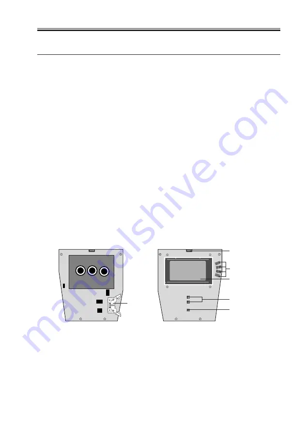
The UIB installed in the front panel of the iR-M1 (see F04-402-01) provides the interface
between the iR-M1 and the user. The front of the user interface board contains circuitry for
the following:
• Activity lights (1 green and 1 red LED)
• Display window (LCD)
• Four line selection buttons
• Up and down button
• Menu button
The UIB cable connects to the cable connector on the back of the UIB and to
motherboard connector J30.
F04-402-01 User interface board layout
UIB cable
connector
(UIB cable
connects
to motherboard)
Activity lights (LEDs)
Line selection
button pads
Display window
Up and down
button pads
Menu button pad
Back
Front
Summary of Contents for FY8-13HR-000
Page 11: ...COPYRIGHT 2001 CANON INC 2000 2000 2000 2000 NM PDL REV 0 JULY 2001 CHAPTER 1 INTRODUCTION ...
Page 26: ...COPYRIGHT 2001 CANON INC 2000 2000 2000 2000 NM PDL REV 0 JULY 2001 CHAPTER 3 INSTALLATION ...
Page 81: ...COPYRIGHT 2001 CANON INC 2000 2000 2000 2000 NM PDL REV 0 JULY 2001 CHAPTER 5 TROUBLESHOOTING ...
Page 98: ...COPYRIGHT 2001 CANON INC 2000 2000 2000 2000 NM PDL REV 0 JULY 2001 CHAPTER 6 PARTS CATALOG ...
Page 102: ...COPYRIGHT 2001 CANON INC 2000 2000 2000 2000 NM PDL REV 0 JULY 2001 APPENDIX ...
Page 105: ...PRINTED IN U S A 0701AB00 This publication is printed on 100 recycled paper ...


