background image

No. D17-6512

D17-6522

Digital Video Camera

CANON INC. 2001

Canon Inc.

Digital Imaging Products Service Dept.

First Edition : Sep. 2001

First Print : Sep. 2001

NTSC

Video Product

ELURA20 MC A

ELURA10 A

ELURA20 MC A

ELURA10 A

c

Summary of Contents for ELURA10 A

Page 1: ...6512 D17 6522 Digital Video Camera CANON INC 2001 Canon Inc Digital Imaging Products Service Dept First Edition Sep 2001 First Print Sep 2001 NTSC Video Product ELURA20 MC A ELURA10 A ELURA20 MC A ELURA10 A c ...

Page 2: ...tch Positions 1 44 6 3 3 Switching the Camera Mode Switching the Program AE Mode 1 45 7 Others 1 46 7 1 Green Mode 1 46 7 2 On Screen 1 46 7 3 Headphone with Docking Unit DU 300 Connected Speaker 1 46 7 4 Battery Level display Warning Displays and Low Power Power Shutoff 1 47 7 5 System Data Display 1 47 7 6 Data Code display 1 47 7 7 MP Tape Capability 1 47 7 8 Warning Buzzer 1 47 7 9 Using Analo...

Page 3: ...es 1 51 7 16 2 Copying 1 52 7 16 3 Card Mix 1 53 7 16 4 Card Playback 1 53 7 16 5 Image Protecting Setting 1 54 7 16 6 Print Mark Setting 1 54 7 16 7 Image Erase 1 54 7 16 8 Format 1 55 7 16 9 Card Review 1 55 7 16 10 Image Setting 1 55 7 16 11 Forward Skip for Card Playback 1 56 ...

Page 4: ...atures Compact vertical magnesium alloy body 1 4 inch progressive scan 680 000 pixel CCD RGB primary color filters 2 5 inch 200 000 Pixel LCD monitor Digital input output DV jack analog input output AV insert function Card still image recording multi media card SD memory card capability MC model only Card mix function MC model only SDL mode max recording time 240 min ELP mode using 80 min tape Mul...

Page 5: ...ELURA20 MC A ELURA10 A CHAPTER 1 GENERAL DESCRIPTION OF PRODUCT 1 2 External Appearance Fig 1 1 ...

Page 6: ...r weighted Full auto mode Auto mode Sports mode system averaged metering Portrait mode Low light mode Evaluation metering 128 sectors spotlight mode surf sand snow mode Exposure AE lock adjustment Exposure compensation after AE lock AE shift Gain setting Higher sensitivity Backlight compensation Shutter speed High speed shutter 6 steps 1 60 1 100 1 250 1 500 1 1000 1 2000 Slow shutter 1 step 1 30 ...

Page 7: ...save after 5 min recording pause Power shutoff Displayed character recording Audio 16 bits 2 ch 48KHz 12 bits 4 ch 32KHz No sync 4 ch recording Wind cut ON OFF switch for built in microphone only EVF Size 0 44 inch color TFT Number of pixels 113 000 pixels Brightness adjustment Color adjustment Portable Monitor LCD Size 2 5 inch Number of pixels 200 000 pixels Brightness adjustment Portable Mirror...

Page 8: ...put output DU 300 capability input output DU 300 capability AV jack input output RCA pin also used for VA also used for VA Edit capability LANG jack DU 300 capability World clock Character title Speaker Warning buzzer Tally lamp Remote control 1 2 capability Accessory shoe Video ID ID1 Recording LP mode SDL E SP E LP Custom key Index screen key MC model only Mix slide show key MC model only DV con...

Page 9: ... Tape thickness 7µm 5 Camera 5 1 Video element 1 4 1 4 inch type progressive scan CCD 5 1 1Number of pixels Total number of pixels approx 680 000 Effective number of pixels approx 360 000 5 1 2 Filters RGB primary color filters 5 1 3 Color separation system Differential read out type 5 1 4 Signal configuration NTSC standard color video signal 5 1 5 Scan system 525 lines x 60 fields 30 frames 5 2 O...

Page 10: ... snow mode low light mode 5 5 2 Light metering system Below center weighted averaging metering Full auto Mode Auto Mode Sports Mode Portrait Mode Low Light Mode Full frame averaged metering 128 sector evaluation metering Spotlight Mode Surf Sand Snow Mode Frame division 128 sectors 16 vertical x 8 horizontal 5 5 3 Exposure compensation function AE lock AE lock by AE shift button operation AE lock ...

Page 11: ...d the mode display disappears when the fader ends Effects Continuous effects are possible until turned off Multi screen Images are captured and displayed on several screens at fixed intervals or as indicated manually Displays continue until turned off Card mix The sample images supplied and images recorded on cards can be mixed and displayed with images captured with the camera 5 10 1 Fader Audio ...

Page 12: ...ing and the VCR modes menu selection 5 12 9 Selftimer 10 sec Approximately 2 sec when the wireless controller WL D75 WL D76 is used 5 12 10 Headphone volume adjustment Adjustment is possible using the multi dial 6 Recorder unit 6 1 Recording functions Camera recording DV input recording analog input recording 6 1 1 Recording format Personal DVC SD specifications 6 1 2 Tape speed SD specifications ...

Page 13: ...3 KΩ or less Output signal level 10dBv 47 KΩ load Frequency response 60Hz 16KHz 1KHz standard 3dB Audio signal S N ratio Microphone input 48dB or more External microphone input 48dB or more using Docking Unit DU 300 6 7 3 S video jack using Docking Unit DU 300 Signal configuration NTSC Y C separate video signal Video signal 1Vp p Brightness sync signal Color signal 0 286Vp p color burst signal Bri...

Page 14: ... once when Fade mode is displayed mode display turns OFF when fader ends Effects Continuous effects are possible until turned OFF Multi screen Images are captured and displayed on several screens at fixed intervals or as indicated manually Displays continue until turned OFF 6 9 1 Fader Audio synchronized fader Auto fade Japanese models white fade overseas models black fade wipe left right scroll a...

Page 15: ...rence city the city for which the clock time has been set has been set the date and time of the selected city will automatically be changed to the local date and time and recorded on the photo when a photo is taken 6 10 8 Speaker Built in With volume adjustment 6 10 9 Battery charge function None 7 Terminals 7 1 DV terminal Special 4 pin connector IEEE 1394 compatible both input and output 7 2 S v...

Page 16: ...ediaCard Card Reader CB 400 Car Battery Adapter BP 406 BP 412 and BP 422 Battery Packs DC 400 DC Coupler CA 400 Compact Power Adapter TV VCR SC 1000 Soft Carrying Case S 150 S video Cable DU 300 Docking Unit STV 250N Stereo Video Cable Digital Device Personal Computer SC A50 Soft Carrying Case CV 150F DV Cable SA 1 Adapter Bracket Stereo Microphone commercially available DU 300 Docking Unit ZR 100...

Page 17: ...oom stopped W T Zooming to Tele W T Zooming to Wide W T Hand jitter compensation display Hand jitter compensation ON Hand jitter compensation OFF No display Recording mode display SD mode SP recording LP recording SDL mode SP recording E LP recording E Operation mode display Mirror mode LCD Recording Recording pause Cassette ejected Stopped Rec search Rec search 5 Viewfinder LCD Display Internal D...

Page 18: ...e Spotlight mode Surf snow mode Low light mode Program AE mode menu Tape counter display Time code no frame display When indeterminate Zero set memory M M M When indeterminate M EXP lock display Minimum exposure value Standard exposure value Maximum exposure value AE No display Timer display Remaining tape display Tape end When indeterminate Tape warning display blink Other No display ...

Page 19: ...ith power supply adapter mounted No display Shutter speed display 1 60 sec 1 100 sec 1 250 sec 1 500 sec 1 1000 sec 1 2000 sec Auto No display Button type lithium battery low level warning display Remote control cord display When cord setting 1 is selected When cord setting 2 is selected Remote control receptor OFF White balance display When set Blinks in WB setting or NG Indoor preset Lights up c...

Page 20: ...epia is selected When mosaic is selected When multi screen is selected When feature off is selected No display Window cut display Window cut ON No display Window cut OFF OFF External microphone connected Date time display When date and time are not set Audio mode display When 16 bits is selected When 12 bits is selected 16 9 mode display When the 16 9 mode is selected Other No display Half way pre...

Page 21: ...elected 12 bit mix variable is selected 16 bit No display Audio mix ratio display When ST 1 ST 2 1 0 When ST 1 ST 2 1 1 When ST 1 ST 2 0 1 Record mode display SD mode SP recording LP recording SDL mode SP recording E LP recording E Operation mode display Recording Pause When the cassette is ejected When stopped Play Fast forward Rewind No tape Fast forward play 2 speed play 1 speed play Forward sl...

Page 22: ...ch FF return REW return AV insert pause AV insert record Audio dubbing pause Audio dubbing Tape counter Time code display When no setting Zero set memory Same as in Camera mode Remaining tape display Same as in Camera mode Audio dubbing insert or search display When AV insert is selected When dubbing is selected Date search Freeze frame photo search Other than search No display Battery level displ...

Page 23: ... Data code setting Camera data Date and time Date and time camera data Time setting Date setting Camera data Aperture value display The aperture value for this product is F1 6 and more Aperture fully closed This product does not have a fully closed When no setting aperture function Shutter speed display The shutter speeds for this product are 1 30 sec 1 60 1 2 000 sec When no setting Time display ...

Page 24: ... setting selected When no setting Wind cut display Same as in Camera mode Audio data display When the audio dubbing audio input terminal selected When the audio dubbing microphone input terminal is selected Audio mode display Same as in Camera mode 16 9 mode Same as in Camera mode DV input DV input DV IN Other No display ...

Page 25: ...rd image quality display Program AE mode display Same as in Camera mode Card access display Card remaining capacity display No card blinks red frames is 9999 or more green When the number of recordable frames is 99 green When the number of recordable frames is 5 yellow When the number of recordable frames is zero 0 red EXP lock display Same as in Camera mode Focus mode display Same as in Camera mo...

Page 26: ...ttery low level Same as in Camera mode warning display Remote control code display Same as in Camera mode White balance display Same as in Camera mode Battery low level warning display Same as in Camera mode Condensation warning display Same as in Camera mode Date display Same as in Camera mode Date time only Photo button partially pressed Same as in Camera mode lock display ...

Page 27: ...n Card review mode display Card record image display Same as the card record image display in Card record mode Card access display Writing to card Red display sequential display Reading from carad Green display sequential display Card remaining capacity display No card Checking card level No remaining capacity 99 frames remaining ...

Page 28: ... OF PRODUCT 1 25 MENU INDICATION NORTH AMERICA MODEL REMARKS Image size display Dot horizontal Image protect Image protect set cancel Image delete mode Shift to image delete screen Return Exit card review mode Image protect set cancel Image delete screen ...

Page 29: ...EMARKS Card Play Mode M Print mark display Protect display DCF file name display Directory number 100 file number 0001 Directory number 998 file number 9900 Card access display Writing to card Red display Sequential display Reading from card Green display Sequential display 5 4 Card Play Mode MC Model only ...

Page 30: ...age number display No card Checking number of cards recorded Zero 0 card recorded 9th of 99 cards recorded 99th of 99 cards recorded 9900th of 9900 cards recorded Image size Dot Horizontal Vertical Data display Same as in VCR mode Date time only Slide show M Slide show operation guide display slide show in progress ...

Page 31: ...attery BLK WHT SEPIA MOSAIC M S SPEED MANUAL MODERATE Lithium battery FAST MODERATE SLOW M S SPLIT 4 4 Lithium battery 9 16 RETURN CARD MIX Shift the Card Mix Screen Displays CAMERA SET UP SHUTTER AUTO AUTO Lithium battery 1 60 1 100 1 250 1 500 1 1000 1 2000 DIGITAL ZOOM ON ON Lithium battery OFF IMAGE S ON ON Lithium battery OFF 16 9 ON OFF Lithium battery OFF WHIT BAL AUTO AUTO Lithium battery ...

Page 32: ...P DISP SET TP BRIGHTNESS 1 Lithium battery MIRROR 1 ON ON Lithium battery OFF TV SCREEN ON ON Lithium battery OFF D T DISPLAY 1 ON OFF Lithium battery OFF RETURN SYSTEM WL REMOTE 2 Lithium battery OFF TALLY LAMP 1 ON ON Lithium battery OFF BEEP 1 ON ON Lithium battery OFF T ZONE DST 2 LONDON N Y Lithium battery LONDON PARIS PARIS CAIRO MOSCOW DUBAI KARACHI DACCA BANGKOK H KONG TOKYO SYDNEY SOLOMON...

Page 33: ... REC MODE SP SP Lithium battery LP E SP E LP OUTPUT CH 1 L R L R Lithium battery L L R R AUDIO DUB AUDIO IN AUDIO IN Lithium battery MIC IN WIND SCREEN ON ON Lithium battery OFF AUDIO MODE 16 bit 12 bit Lithium battery 12 bit RETURN CARD SET UP QUALITY FINE FINE Lithium battery STANDARD IMAGE NOS 1 RESET CONTINUOUS Lithium battery CONTINUOUS SHTR SOUND ON ON Lithium battery OFF RETURN CARD OPER CO...

Page 34: ...Menu screen only 2 On other screens DATA CODE is displayed only when it is turned on MAIN MENU ITEM SUB MENU ITEM SETTING ITEM DEFAULT BACKUP DISP SET UP D TIME SEL 2 DATE DATE TIME Lithium battery TIME DATE TIME RETURN SYSTEM WL REMOTE Lithium battery OFF TALLY LAMP ON ON Lithium battery OFF BEEP 1 ON ON Lithium battery OFF REUTRN RETURN ...

Page 35: ...M SET UP SHUTTER AUTO AUTO Lithium battery 1 60 1 100 1 250 1 500 1 1000 1 2000 D ZOOM ON OFF Lithium battery OFF IMAGE S ON ON Lithium battery OFF WHIT BAL AUTO AUTO Lithium battery SET INDOOR OUTDOOR RETURN CARD SET UP QUALITY FINE FINE Lithium battery STANDARD FILE NOS 1 RESET CONTINUOUS Lithium battery CONTINUOUS SHTR SOUND 1 ON ON Lithium battery OFF RETURN DISP SET UP BRIGHTNESS 1 Lithium ba...

Page 36: ...E SEL is displayed only when D T DISPLAY is OFF WL REMOTE OFF is always displayed MAIN MENU ITEM SUB MENU ITEM SETTING ITEM DEFAULT BACKUP SYSTEM T ZONE DST 2 LONDON N Y Lithium battery LONDON PARIS PARIS CAIRO MOSCOW DUBAI KARACHI DACCA BANGKOK H KONG TOKYO SYDNEY SOLOMON WELLGTN SAMOA HONOLU ANCHOR L A DENVER CHICAGO N Y CARACAS RIO FERNEN AZORES AZORES D TIME SEL 2 JAN 1 2001 JAN 1 2001 Lithium...

Page 37: ... DISPLAY EXECUTE PRINT MARK Shift to Delete All Print Marks IMAGE ERASE CANCEL CANCEL SINGLE ALL FORMAT CANCEL CANCEL EXECUTE RETURN CARD SET UP PROTECT Shift to Image Protect Mode INDEX DISPLAY PRINT MARK Shift to Print Mark Mode RETURN VCR SET UP REC MODE SP SP Lithium battery LP RETURN DISP SET UP BRIGHTNESS 1 Lithium battery DISPLAY ON ON Lithium battery OFF D TIME SEL 2 DATE DATE TIME Lithium...

Page 38: ...RA10 A CHAPTER 1 GENERAL DESCRIPTION OF PRODUCT 1 35 5 6 Card Mix Screen Displays MENU INDICATION NORTH AMERICA MODEL REMARKS Card mix selection screen Mix key setting screen Mix level setting screen Slide show screen ...

Page 39: ...ELURA20 MC A ELURA10 A CHAPTER 1 GENERAL DESCRIPTION OF PRODUCT 1 36 MENU INDICATION NORTH AMERICA MODEL REMARKS Index screen Image protect screen Print mark screen ...

Page 40: ...RA20 MC A ELURA10 A CHAPTER 1 GENERAL DESCRIPTION OF PRODUCT 1 37 MENU INDICATION NORTH AMERICA MODEL REMARKS Copy screen Copy selection screen Copy execute screen Copy selection screen Copy execute screen ...

Page 41: ...LURA10 A CHAPTER 1 GENERAL DESCRIPTION OF PRODUCT 1 38 MENU INDICATION NORTH AMERICA MODEL REMARKS Image delete screen Image delete selection screen One image deletion Deletion in progress warning All images deletion ...

Page 42: ...ELURA20 MC A ELURA10 A CHAPTER 1 GENERAL DESCRIPTION OF PRODUCT 1 39 MENU INDICATION NORTH AMERICA MODEL REMARKS Format screen Format confirmation screen Format execution screen ...

Page 43: ...sation is detected if cassette is loaded this message will be followed by REMOVE THE CASSETTE THE TAPE IS SET FOR ERASURE PREVENTION Displayed in the VCR mode when REC is pressed in a mode in which recording is possible but the cassette is set for erase protection In the Camera mode this message is displayed when the power is turned on when the START STOP button is pressed and when a cassette is l...

Page 44: ...a noncompatible JPEG image or an image with damaged data MC model only PRINT MARK ERROR Displayed when there are too many 51 or more print marks or the mark file cannot be edited MC model only NO CARD Displayed when there is no card in the body socket MC model only NO IMAGES Displayed when there are no images on a card to play back MC model only THE CARAD IS SET FOR ERASURE PREVENTION Displayed wh...

Page 45: ...on Type Lithium Primary Battery Items other than the menu items backed up by the main power supply or backup power supply button type lithium primary battery Item Default Remarks Digital zoom position Optical Tele WB date SET Date time setting auto date 2001 1 1 12 00AM Menu cursor position Uppermost position Time code Mix balance Center Headphone volume Center Speaker volume Center Mechanical err...

Page 46: ...imer ON OFF Reset to OFF On screen ON OFF Backup Zero set memory counter value CAM Backup Camera Card recording menu item setting Digital effect selection Backup Independent Fader CAM Backup Independent Effect Backup independent Multi screen speed Backup Independent Multi screen number Backup Independent Card mix key selection CAM MC model only Backup Card mix level CAM MC model only Backup Shutte...

Page 47: ...ote control code setting Backup Record mode setting Backup Data code setting Backup Date time select setting Backup LCD Brightness adjustment Backup Text display during playback ON OFF Backup Auto date time display ON OFF Backup Bilingual setting Reset to main sub Audio dubbing input setting Backup Wind cut ON OFF Backup Line in audio mode setting Backup Warning buzzer ON OFF Backup Image quality ...

Page 48: ...de Card recording mode MC model only menu item setting Digital effect selection Backup Independent Backup Independent Fader CAM Backup Independent Backup Independent Effect Backup Independent Backup Independent Multi screen speed Backup Independent Backup Independent Multi screen number Backup Independent Backup Independent Card mix selection CAM MC model only Backup Backup Card mix level CAM MC m...

Page 49: ...Text on line out will be white during on screen LCD panel and CVF text will be in color The display defaults are ON in the Camera mode and OFF in the VCR mode 7 3 Headphone with Docking Unit DU 300 Connected Speaker The speaker is OFF in the Camera mode The speaker is ON during normal VCR mode playback and the volume can be adjusted with the Multi dial Headphone volume can be adjusted with the Mul...

Page 50: ...as well as ESP and ELP recording is not possible with MP tape Even if LP ESP or ELP is selected from menu the SP mode will always be set when a tape is loaded LP playback is possible with tapes recorded in the LP mode 7 8 Warning Buzzer The warning buzzer will sound melodically in the following cases REC PAUSE includes audio dubbing and AV insert REC PAUSE Peep 4KHz beep 2KHz boop 1KHz Camera mode...

Page 51: ...ding Recording will stop The Table below Shows the Input and Output Status for Each Mode There is no signal when there is no line input 7 10 VIdeo ID1 Detection Output Capability 1 S1 signal output When 16 9 images are output from the S video jack in the Full Squeeze mode compressed to 4 3 an identification signal is output to automatically return them to 16 9 images for wide monitors with S1 capa...

Page 52: ...ubbing Signal Input Source The audio dubbing input source is selected from the VCR menu Either of two items can be selected Line AV mini jack or Mic When Mic is selected input will be from the external microphone if one is connected otherwise input will be from the built in microhone 7 12 3 Audio Dubbing Operation 1 In the VCR mode position and pause the tape to be dubbed then press the dubbing ke...

Page 53: ...AV Insert mode will not be canceled and status 1 AV Insert pause will return AV Insert can also be canceled by pressing the AV Insert key of the remote control during AV Insert Pause Also if the Zero Set Memory key of the remote control is pressed at the tape position where AV insert is to be ended operation will automatically stop and AV insert will be canceled when that position is reached after...

Page 54: ...and jitter compensation function has been restricted will light green 3 Frame the subject and fully press the Photo key will go out and the image will be recorded on the card at the instant the key is fully pressed During the card recording the red access display will blink toward the Card mark During this time the image being recorded will stop freeze on the LCP panel or CVF so the result can be ...

Page 55: ...4 When Execute has been selected and set the Copy Execute screen tape data is displayed in the upper left corner and card data is displayed in the lower right corner will open and the copy operation will start During the copy operation a still image search of the tape will be performed starting from the current tape position The still images discovered during the search are recorded as still image...

Page 56: ...gs again When the Power switch has been set to another mode When the Photo Mode switch has been set to Green mode 7 16 4 Card Playback a Normal Playback Slide Show 1 Set the Power switch to Card play mode The Power lamp will light green and if a card has been loaded and if there are images the last image will be displayed If no images have been recorded a blue background will be displayed and the ...

Page 57: ...e unwanted images There are two image erase methods One method is used after card recording has ended In the other method only images selected by using card review are erased while a card is still being used Image Erasure after Card Recording has Ended 1 Set the Power switch to Card play mode When the still images are displayed press the Menu key to open the Card play menu screenh and select the C...

Page 58: ...sly recorded card mix sample images Images and files from other equipment or PC 7 16 9 Card Review When key is pressed on the Card recording mode the Card still image check display will appear and the mode will be changed to the Card Still Image Check mode For the still images read out the Image Protect or Delete One Image operation is available To cancel the mode select Return with the multi dial...

Page 59: ...han 1 the display no will restart re versely from total count Card Related Cautions for All Modes Cautions When the red mark this mark is white in the Mirror Photo mode Memory mode and in the Line Out screen is blinking facing toward the Card mark this means that the card is being written so never remove the card disconnect the battery pack or AC power cord at this time Such actions can damage the...

Page 60: ...ra Card Signal Processing 1 7 3 3 Recorder Signal Processing 1 9 3 4 Audio Signal Flow 1 10 4 System Control Servo 1 11 4 1 Outline of System Control Servo 1 11 4 2 Major Functions of Each Microcomputer 1 12 4 3 Servo Control 1 12 4 4 Error Detection 1 13 4 4 1 Error Detecting Conditions 1 13 4 4 2 Processing after Error Detection 1 13 4 5 IC Terminal Functions 1 14 4 5 1 CAMERA MI COM IC1401 1 14...

Page 61: ...a data IC1404 EVR D A CONVERTER EVR D A converter for camera adjustment CVF Section IC1501 EVR D A CONVERTER D A converter for EVR of EVF section IC1502 EVF DRIVER EVF LCD CVF drive IC1503 SWITCH EVF display character mixing switch Video Section IC2000 VRP2 Recording Playback head amplifier IC2100 VIF2 Analog video input output signal processing IC2301 VIC2 Digital VCR signal processing LSI SDRAM ...

Page 62: ...ignal sampling AGC A D converter IC1005 VCO PLL Camera clock phase lock IC1006 INVERTER Inverter amplifier for clock IC1007 8 9 AND AND gate for clock voltage conversion 4 CCD P C B IC1000 CCD CCD image sensor 5 AUDIO P C B IC701 OPE AMP Operational amplifier for microphone IC801 AUDIO INTERFACE Analog input output signal processing IC802 A D D A CONVERTER Audio signal A D D A conversion IC803 5 0...

Page 63: ...ignal from pin 4 SUB MI COM receives this and recognizes that the main power supply is connected then carries out initialization of the mechanisms after which it enters a standby status In this condition SUB MI COM performs detection of switches related to startup and outputs VTR ON H signal from pin 48 upon detection By means of VTR ON signal the recorder power supply is started up and the MAIN M...

Page 64: ...motor Recorder motor driver CVF backlight power supply 2 UNREG DC DC FU3201 DC DC CONVERTER CONTROL IC power supply 3 VTR UNREG FU3202 1 7V system power supply CCD 6 5V 15V LCD12V E3V LANC LCD backlight power supply 4 UNREG 3V FU3202 2 3V system 3V system power supply Fig 2 2 MAIN P C B 9 1 TP3203 4 FU3201 TP3201 2 1 2 4 3 FU3202 UNREG VS FROM BATTERY TERMINAL UNREG DC DC VTR UNREG UNREG 3V 1 2 4 ...

Page 65: ...VS IN OUT DVDD 4 7V HA 4 7V DIF 2 8V MO 5V IC3203 4 7V REG 10 21 Q3213 REG PWM CH 1 VTR UNREG VTR ON Q3209 10 1 2 LCD 12V 11 19 Q3212 REG PWM CH 2 VTR UNREG CAM ON Q3208 10 2 2 CCD 15V 13 16 Q3211 14 REG PWM CH 3 VTR UNREG CCD 6 5V 50 5 1 4 36 Q3216 Q3201 5 Q3227 REG PWM CH 2 UNREG 3V IN OUT ON HA3 0V DVDD 3 0V A3 0V CARD 3 0V LCD 3 0V CAM 3 0V CAM 2 3V AVDD 2 3V DVDD 2 3V IC3219 2 8V REG 56 33 Q3...

Page 66: ... circuit and the flow of video and audio signals Fig 2 4 LENS IC1000 CCD MMC P C B AUDIO P C B CCD P C B CA P C B LCD P C B MAIN P C B Card IC1101 DIC4 IC4002 SDRAM MC model only IC2000 VRP2 LCD CVF LCD REC PB HEAD IC2600 CG IC1502 EVF DRIVER IC902 LCD DRIVER IC2100 VIF2 DV AV MIC IC802 A D D A IC801 AIF JACK FPC VIDEO AUDIO IC4003 SIC SDRAM VIC2 IC1102 SDRAM IC1003 CDS AGC A D IC1001 TG IC2301 ...

Page 67: ...d to the playback signal CH 2 is for input and CH 1 for output SDRAM IC1102 Field memory for signal processing digital effect 2 Card MC model only SIC IC4003 When the card function is not operated camera signal is sent directly to VIC2 Video signal capture function Video signal switch card mix function JPEG compression decompression Image enlargement reduction Card interface SDRAM IC4002 Image dat...

Page 68: ...C4002 the image captured in SIC CH 1 3 SIC applies JPEG compression to the image and starts writing into Card 4 When SIC finishes write in to Card VIC2 releases the capture function At playback recording Image from VIC2 appearing at LCD and video output is A DATA image via SIC DIC4 At DV input Image from VIC2 appearing at LCD and video output is the image captured at 1 Card Playback 1 SIC decompre...

Page 69: ...from VIC2 is amplified at VRP2 and is recorded on magnetic tape while undergoing head switching of CH 1 CH 2 with a switching pulse At playback the head output signal is amplified and sent to VIC2 VIF2 IC2100 Related parts are reduced in comparison to conventional VIF and a sync separation function for analog line input is added Y and C signals sent from VIC2 are output as Y C signals for S termin...

Page 70: ...tput signal Also the shutter sound at card recording from the CAMERA MI COM and the beep tone issued at ejection from the MAIN MI COM are added to the speaker output signal in AIF A D D A IC802 Carries out analog digital signal conversion Sampling frequency is output from VIC2 and is Fs 32 KHz or Fs 48 KHz depend ing on the audio mode Quantization bit number is 12 bits in case of 32 KHz or 16 bits...

Page 71: ...C B LCD P C B IC1001 TG IC1404 EVR IC901 EEPROM IC902 LCD DRIVER IC1501 EVR IC1502 EVF DRIVER IC2600 CG IC201 EEPROM IC1403 EEPROM IC1304 MOTOR DRIVER IC3201 DC DC CONVERTER IC1401 CAMERA MI COM DIAL SW IC100 MAIN MI COM IC1101 DIC4 IC4003 SIC IC4001 V53 IC230 VIC2 IC203 SUB MI COM IC2100 VIF2 IC801 AIF MULTI JACK LANC JACK DOCKING UNIT DU 300 IC200 VRP2 IC202 LANC I F Card IC1003 CDS AGC A D LENS...

Page 72: ...rging control Following are the major functions Key input Remote control input Power ON OFF control MIC Memory In Cassette control 3 CAMERA MI COM IC1401 Carries out lens control and camera signal processing Following are the major functions CCD drive control AE AF AWB control EIS Electric Image Stabilizer control Zoom key input 4 3 Servo Control Servo control is made by the MAIN MI COM and VIC2 t...

Page 73: ...ror detecting time Starting 5sec Steady 0 5sec Capstan error Error detecting mode Starting steady C FG FG frequency when steady 1347Hz Error detecting level Starting 80 max Steady 100Hz max Error detecting time Starting 2sec Steady 0 5sec Reel error Error detecting mode Normal UNLOAD T S REEL FG Error detection Normally C FG number per reel FG cycle is C FG 2 4 1347 or more UNLOAD Reel FG half cyc...

Page 74: ...RET O Lens LED illumination 5 0 9023 3 22 X F PSV O Focus power save 5 0 9023 4 23 X Z PSV O Zoom power save 5 0 9023 5 24 F RES SW I Focus reset detection Pull Down 5 0 9023 6 25 Z RES SW I Zoom reset detection Pull Down 5 0 9023 7 26 X PC CS O For AF debugging 5 0 9024 0 27 CAM DIC RST O CAM DIC RST to MODE 5 0 9024 1 28 X PC ACK I O For AF debug WB debug 5 0 9024 2 29 X DIC4 RST O Unused 5 0 90...

Page 75: ...d 88 VCCP CAM 3V 89 VSSP GND 90 1 Unused 92 DIC SCLK1 O DIC serial clock 5 0 9028 7 93 DtoC DATA1 I DIC serial data receive 5 0 9028 6 94 CtoD DATA1 O DIC serial data send 5 0 9028 5 95 6 Unused 97 SCLK0 O EEPROM serial clock 5 0 9028 2 98 SDI0 I EEPROM serial data receive 5 0 9028 1 99 SDO0 O EEPROM serial data send 5 0 9028 0 100 VCC CAM 2 3V 101 VCCP CAM 3V 102 JTAG I FP JTAG terminal Pull Up 1...

Page 76: ... mode microcomputer communication request 5 0 902C 2 Pull Down 146 X PC REQ I O For AF debug WB debug for development 147 ADJ REQ I For plant adjustment Pull Down 148 9 Unused 150 VCC CAM 2 3V 151 VSS GND 152 156 Unused 157 VCCP CAM 3V 158 VSSP GND 159 176 Unused 177 XCIN CAM 2 3V 178 VSSR GND real time clock GND 179 XCOUT O Unused 180 VCCR CAM 3V real time clock power supply 181 AVREF A D referen...

Page 77: ...ss bus VIC2 7 2 D3 5 21 EADDR4 O Address bus VIC2 7 2 D3 4 22 EADDR3 O Address bus VIC2 7 2 D3 3 23 EADDR2 O Address bus VIC2 7 2 D3 2 24 EADDR1 O Address bus VIC2 7 2 D3 1 25 EADDR0 O Address bus LSB VIC2 7 2 D3 0 26 EDATA15 I O Data bus MSB VIC2 7 2 D4 7 27 EDATA14 I O Data bus VIC2 7 2 D4 6 28 EDATA13 I O Data bus VIC2 7 2 D4 5 29 EDATA12 I O Data bus VIC2 7 2 D4 4 30 EDATA11 I O Data bus VIC2 ...

Page 78: ...O Audio emphasis setting 7 2 DB 5 74 A EMP1 O Audio emphasis setting 7 2 DB 6 75 AUD ON O Speaker headphones power supply control 7 2 DB 7 76 BUZZER CARRIER2 O Buzzer 2 output 7 2 DA 0 77 BUZZER CARRIER1 O Buzzer 1 output 7 2 DA 1 78 RESERVE2 I V53 firmware update status detection 7 2 DA 2 79 TEST1 For factory adjustment 7 2 DA 3 80 EVF SENS O IC chip select for EVF drive 7 2 DA 6 81 LANC IN I LAN...

Page 79: ...D 123 XOUT O 20 MHz 124 PLLCVCC DVDD2 3V 125 PLLCAP External capacitor for PLL is connected to this terminal 126 PLLVSS GND 127 OSDC CS O OSDC IC chip select output 7 2 D1 0 128 OSDC RESET O OSDC reset output 7 2 D1 1 129 VSSB GND 130 VCCB DVDD3V 131 O Unused 7 2 D1 2 132 O Unused 7 2 D1 3 133 O Unused 7 2 D1 4 134 FCHO I Factory process mode soft debug terminal 0 7 2 D0 0 for factory adjustment 1...

Page 80: ...ion direction signal output 7 2 E0 3 172 TAPE LED O Tape LED illuminant control 7 2 E0 2 173 N C O 7 2 E1 1 174 DRUM ON O Drum motor start stop signal output 7 2 E0 1 175 SELCSLP O Drum driver control 7 2 E1 0 176 REEL LED CONT O Reel sensor LED illumination power save 7 2 E0 0 177 XCIN I 32 KHz 178 VSSR GND 179 XCOUT O 32 KHz 180 VCCR Power flag is set when VCCR decreases to 0 1 V or less once th...

Page 81: ...tection 7 3 F9 6 21 EJECT SW I EJECT switch detection 7 3 F9 5 22 LANC ON I LANC power ON detection 7 3 F9 4 23 LI3 DET I Detected power loss of lithium battery for backup 7 3 F9 3 24 MAIN SW2 I Power swich detection 7 3 F9 2 25 MAIN SW1 I Power switch detection 7 3 F9 1 26 MAIN SW0 I Power switch detection 7 3 F9 0 27 VTR PW LED O VTR mode POWER LED control 7 3 F8 7 28 CAM PW LED O Camera mode PO...

Page 82: ... 1 General 1 4 4 2 Service Mode Indications 1 4 5 Description of Service Modes 1 5 5 1 Error Rate 1 5 5 2 Mechanical Error Indications 1 6 5 3 Camera Special Commands 1 7 5 4 Checking the Lens Resetting 1 8 5 5 Functional Check of Control Keys and Switches 1 8 5 5 1 Voltage Range for A D Input Key 1 8 6 Service Hints 1 9 6 1 Arrangement of Circuit Boards 1 9 6 2 Current Consumption Check 1 9 7 Tro...

Page 83: ...r 5600K DY9 2040 000 Replacement Filter CCA W12ø46mm DY9 2046 000 Camera electrical adjustment Remote Commander RM 95 DY9 1349 000 Service mode electrical adjustment CZ Siemens Chart DY9 1372 000 CZ adjustment Same chart as the covention model s Item Name Item Number Purpose Remarks Logenest Lambda A 74 CY9 8102 000 Lubrication Lens Grease GE C9 CY9 8043 000 Lubrication Lens Grease GE X8 CY9 8044 ...

Page 84: ...er connect the cable of the Left Cover unit with the CN200 P DIAL Connecting the TP203 and TP204 MAIN P C B to ground can trun on the power also 4 Operation by a LANC Remote Controller is possible by connecting the Docking Unit DU 300 with the Multi Connector 5 The power is suppliable via the DC 400 or connecting the Constant Voltage Supplier with the TP3201 3202 DC and the TP3203 3204 DC LANC REM...

Page 85: ...mode Key Functions in Service Mode Fig 3 2 1 HOLD SW 2 PAGE 3 BANK 4 BANK 5 ADDRESS 6 ADDRESS 7 DATA 8 DATA 9 STORE 11 PAGE DISPLAY 12 EJECT 10 MODE SELECT 6 4 5 8 7 No Key name in service mode Function Key name in normal state 1 HOLD Transition to service mode by setting to the HOLD HOLD position 2 PAGE PAGE is incremented by one START STOP 3 BANK BANK is incremented by one EDIT SEARCH 4 BANK BAN...

Page 86: ...ted to the command MAIN CAM SUB microcomputer etc 3 Indicates a message for a special command DATA SUB etc 4 PG Indicates the PAGE being selected 4 to 7 5 BK Indicates the BANK being selected 0 to 7 6 MD Indicates the MODE being selected RD WR 7 ADDR Indicates the ADDRESS being selected in hexadecimal 00 to FF 0000 to FFFF 8 DT Indicates the DATA being read or set in hexadecimal 00 to FF 9 DT Indi...

Page 87: ...rroneous sync block of 64 track AUDIO sync blocks is indicated in two hexadecimal digits FF limitation is imposed on a value exceeding 255 Example 23 is indicated Number of erroneous sync blocks 35 Important After the adjustment set the DT to the product setting press STORE key at 1 of STEP 1 state Fig 3 4 Low ch High ch EO 1 5 E1 1 10 5 Fig 3 5 Low ch High ch hexadecimal decimal AO 2 3 A1 2 2 16 ...

Page 88: ...ror data backed up by Lithium 3V STEP PROCEDURE MONITOR Microcomputer operation MECH ERROR PG BK MD ADDR DT ST 1 1 Make setting shown at right 7 2 RD 01 Error data held only in the POWER ON state is indicated 2 1 Make setting shown at right 7 2 RD 02 Error data backed up by the EEPROM is indicated 3 1 Make setting shown at right 7 2 WR 02 00 2 Press the STORE key RD Completion of backup data reset...

Page 89: ...AIT 2 Press the STORE key RD OK The iris is opened forcibly IRIS CLOSE 1 Make setting shown at right 5 2 WR 3306 WAIT 2 Press the STORE key RD OK The iris is closed forcibly AGC MAX 1 Make setting shown at right 5 2 WR 3307 WAIT 2 Press the STORE key RD OK A value of AGC gain is maximized AGC MIN 1 Make setting shown at right 5 2 WR 3308 WAIT 2 Press the STORE key RD OK A value of AGC gain is mini...

Page 90: ... are provided for the data content which seem rather complicated For other than below use the addresses shown in the Remarks column of the I O port table 4 When carrying out functional checks select the RD mode 5 5 1 Voltage Range for A D Input Key 1 On the MAIN and SUB microcomputers the terminals shown in Fig 3 8 are A D input ports Key and or mode is detected by means of the A D converted volta...

Page 91: ...tatus Measurement condition Product status camera auto mode AF IS OFF LCD ON 0 1A each smaller in case of CVF Preset voltage 7 4V MC model only POWER SW MODE Current Consumption A POWER SW MODE Current Consumption A CAMERA REC PAUSE 0 65 VTR STILL 0 50 REC 0 72 FF REW 0 70 STOP 0 63 CUE REV 0 61 VTR STOP 0 46 CARD REC 0 70 PLAY 0 57 CARD PLAY 0 47 Fig 3 9 CA P C B CVF P C B CCD P C B ZOOM SW UNIT ...

Page 92: ...pply Each microcomputer SUB MAIN CAMERA is started up to carry out system control Check Points 1 Key Inputs Check the key inputs at Power Switch in the SERVICE mode 2 Check of microcomputer to microcomputer communication If the microcomputer to microcomputer communication line is normal the version number of each microcomputer can be indi cated in the service mode Otherwise the communication line ...

Page 93: ... when the picture information in block unit exceeds a limit of processing performance of error correction and the previous picture information is used for compensation Normally if an error rate is worsened considerably by the deterioration of tape quality or head output the symptom appears For this reason when you check the playback picture check the error rate To evaluate the error rate at an abs...

Page 94: ...it 1 4 14 1 15 Disassembly of Right Cover Unit 2 4 15 1 16 Disassembly of LCD Unit 1 4 16 1 17 Disassembly of LCD Unit 2 4 17 1 18 Disassembly of LCD Unit 3 4 18 1 19 Disassembly of LCD Unit 4 4 19 1 20 Disassembly of CVF Unit 4 20 1 21 Disassembly of Lens Unit 1 4 21 1 22 Disassembly of Lens Unit 2 4 22 1 23 List of Screws Used 4 23 1 24 List of Disassembly Photos 4 24 2 Adjustment Procedures 4 2...

Page 95: ...Destination 4 34 2 6 2 Y LEVELAdjustment 4 34 2 6 3 C LEVEL Adjustment 4 35 2 6 4 AGC Initial Value Adjustment 4 35 2 6 5 SWP Adjustment 4 36 2 6 6 C FG Adjustment 4 36 2 6 7 EQ Adjustment 4 36 2 6 8 Battery Voltage Drop Adjustment 4 37 2 7 Tape Path Adjustment 4 37 ...

Page 96: ...low it to remain folded the same as the original part 2 The flat cable has a contact orientation to be engaged with the connector Refer to the instructions in the disassembly procedure diagram and interconnection diagram for boards Lateral engaging connector The instructions are given in the disassembly procedure diagram and board interconnection diagram Contacts are positioned downward board side...

Page 97: ...eparate the AV cover from the Rear Cover Instruction for Supply Finder section Hanal FL778 DY9 3026 000 Shaft and spring parts Hanal FL778 DY9 3026 000 Fig 4 1 Silver Painted M1 7 3mm b Metal M1 7 3 5mm d 5 5mm c Silver Painted M1 7 self tap 3mm a Silver Painted M1 7 Hanal FL 778 3 Lever AV Cover Cassette Cover LCD Unit Finder Unit Rear Cover Hanal FL 778 Shaft and Spring 3 a 3 a 3 c 3 b 3 d 4 2 2...

Page 98: ...d Zoom Key Unit 1 Remove two screws b 1 e 1 2 Detach the Top Cover Mic Cover and Mic Sheet 3 Remove CN1401 and two screws f 2 then detach the Zoom Key Unit Fig 4 2 2 2 Silver Painted M1 7 3mm b Metal M1 4 2mm f 2 5mm e Silver Painted M1 7 CN1401 Top Cover Zoom Key Unit Mic Cover Mic Sheet 1 b 1 e 3 f 3 ...

Page 99: ...polarity when reassembling 2 Remove the Remote Control Window Cover Note on Reassembling 1 When attaching the magnets on the LCD Holder Covers with an adhesive face the red painted sides N down Instruction for Supply Adhesion of magnet DIA BOND No 1663 DY9 3009 000 Fig 4 3 Note on Reassembling 1 2 1 1 Bond applying Position g 4mm Silver Painted M1 7 self tap 1 g Remote Control Window Cover LCD Hol...

Page 100: ...over Unit 1 Detach the Hand Strap 2 Remove four screws d 1 j 1 k 2 3 Detach CN200 and with the Cassette Cover opened remove the Left Cover Unit Fig 4 4 Cassette Cover Left Cover Unit Hand Strap CN200 Metal M1 7 3 5mm d 3 5mm j Black M1 7 self tap 4mm k Metal M1 7 2 d 2 k 2 k 2 j 3 3 3 1 ...

Page 101: ... Unit Note on Reassembling 1 Secure three screws i in order 2 Be careful when wiring the FPC of CN102 Fig 4 5 Note on Reassembling 2 Note on Reassembling 1 1 CN1502 CN102 CN102 CN3201 Right Cover Unit LCD Unit Rest of FPC should be inserted between the metal plate and the P C B and not under the rubber part Screw tightening order 2 5mm i Metal M1 7 Metal M1 7 3mm l 1 i 1 i 1 i 1 i 1 l 1 l 1 l UL T...

Page 102: ...C B Note on Reassembling 1 Be sure to attach the Cushions on the specified positions Fig 4 6 Note on Reassembling 1 2 1 1 1 1 1 2 5mm h Metal M1 7 Metal M1 4 4 5mm m Black M1 4 1 3mm n Lens Ring Unit Mic Unit CVF Unit Cushion Cushion Cushion Align with the ridge line Left reference Align the corners adjust so that upper end of cushion falls into the space and is not placed on the CVF plate Fold th...

Page 103: ...emove three screws h 3 and CN304 CN1301 B to B CN2000 and UL tape and detach the Main P C B Audio P C B and Mic Unit together 4 Remove CN601 and CN3301 B to B and separate the Audio P C B and Mic Unit from the Main P C B Fig 4 7 4 2 2 Audio P C B Audio P C B UL Tape UL Tape Mic Unit Main P C B Main P C B Multi P C B Jack Unit CN3302 CN3301 B to B CN601 B to B CN1301 B to B CN2000 CN92 CN304 CN93 2...

Page 104: ...der has been detached Facing the gear at the rear of main chassis downward may result in damage to it Note on Reassembling 1 When attaching the Recorder Holder note that there should be Rubber pieces at five locations 2 Before using the Insulation Rubber of service parts coat the entire surface with Hanal KS 50M DY9 3047 000 Fig 4 8 Note on Reassembling 1 3 1 Lens Unit Recorder Holder UL Tape UL T...

Page 105: ...over Holder ELURA10 A Note on Reassembling 1 Secure the screws of C Cover in order Instruction for Supply Spring Plate Hanal KS 50 Fig 4 9 Grease applying Position Note on Reassembling 1 3 3 2 2 1 Spring Plate Dial Plate C Cover ELURA20 MC A Switch Knob MMC Cover Unit ELURA10 A SD Cover Holder Double side adhesive tape No 1 No 1 No 2 No 3 Screw tightening Order Hanal KS 50 2 8mm t Metal M1 4 self ...

Page 106: ...mbly of Left Cover Unit 2 1 Remove the Hand Strap 2 Detach six screws u 2 v 1 w 1 h 2 and CN14 then remove the Cassette Rear Cover Fig 4 10 Cassette Rear Cover Hand Strap CN14 2 h 2 u 2 v 2 w 2 5mm h Metal M1 7 2mm u Metal M1 7 Metal M1 7 6mm v Metal M1 7 self tap 3 5mm w 2 2 ...

Page 107: ...N13 CN15 and then MMC P C B 2 Detach one screw h 1 and then the Main Dial Unit Note on Reassembling 1 The speaker wiring at the rear of Main Dial Unit should be run through the A part in Fig 4 11 for connection Fig 4 11 2 1 1 1 1 2 5mm h Metal M1 7 Main Dial Unit MMC P C B CN11 CN13 CN15 A 2 h Note on Reassembling 1 ...

Page 108: ...d Cassette Arm Unit Note on Reassembling 1 Fold the FPC as shown in the figure when connecting it Instruction for Supply Arm guide assembly in Cassette Arm Unit FLOIL C 1Z Fig 4 12 Note on Reassembling 1 Grease applying Position Cassette Arm Unit Left Cover Caution Seal Floil C 1Z Cassette Arm Guide Metal M1 7 1 8mm r 2 5mm i Metal M1 7 Metal M1 7 3mm l Metal M1 7 3mm C 1 i 1 l 1 l 1 r 1 C 1 1 ...

Page 109: ...y 1 and detach the Tripod Plate Note on Reassembling 1 Set the distance between the shadowed part of LCD MAIN FPC and the step part of the Right Cover at 1mm as in the figure Then secure them with the UL tape Fig 4 13 3 2 1 Tripod Plate UL Tape Rear side of right cover Battery Terminal Unit LCD Unit Right Cover Metal M1 7 3mm l Metal M2 0 4 5mm x 4 5mm y Metal M1 7 self tap 2 l 1 x 3 y 1 x LCD MAI...

Page 110: ...Right Cover Note The Recorder Unit is held in place by double side adhesive tape So push it through the hole in the rear of Right Cover by a thin stick so it is raised and then pulled slowly to separate it Also be careful not to damage the FPC when pulling it through the hole in Right Cover Fig 4 14 CAUTION 1 Recorder Key Unit Right Cover Hole ...

Page 111: ...f LCD Unit 1 1 Remove five screws e 5 then detach the LCD Top Cover while being careful with the Claw A Note on Reassembling 1 LCD Top Cover should be assembled after inserting the Claw A Fig 4 15 1 e Silver Painted M1 7 2 5mm Claw A LCD Top Cover 1 e 1 e 1 e Note on Reassembling 1 ...

Page 112: ...e on Reassembling 2 Note on Reassembling 1 1 1 1 h 1 h UL Tape Be sure to cover this element without fail Attach UL tape so that it will not protrude beyond the side edge of the PCB LCD P C B LCD Shield Back Light Unit 1 Pass the Back Light Wire through the hole in LCD P C B 2 Bend the Back Light wire solder it and fold the LCD shield through 180 along the edge of the LCD P C B Before passing the ...

Page 113: ... two screws D 2 peel off the Magnet sheet and detach the Hinge Covers L R Note on Reassembling 1 The magnet has polarities Fig 4 17 Note on Reassembling 1 3 3 2 1 1 LCD Lock Switch Hinge Cover R Hinge Cover R LCD Hinge Unit Magnet Sheet Hinge Cover L Hinge Cover L The side with red paint N should face upward LCD SW FPC Magnet 2 5mm 2 h 1 j 3 D h Metal M1 7 3 5mm j Black M1 7 self tap 4mm D Black M...

Page 114: ...em with the Kapton tape DY9 3052 000 so that it covers the LCD FPC 2 After wiring the LCD FPC around the Hinge Unit be sure to wrap it with the LCD FPC Sheet before assembling Instruction for Supply LCD FPC LCD FPC Sheet Hanal FL778 Kapton Tape Tape Kapton DY9 3052 000 Fig 4 18 LCD Hinge Unit LCD FPC LCD FPC Sheet Hanal FL778 LCD FPC Align outside and attach tape securely Align outside and attach ...

Page 115: ...Unit 3 Detach the LCD Stopper CVF Panel and Mask Note Detach the LCD Stopper while being careful about the four claws 4 Remove the Clamp Washer Finder Lever and Spring Fig 4 19 4 3 2 2 1 1 1 Rubber Back Light Unit Spring Clamp Washer Finder Lever Cushion Mask Claws CVF Panel LCD Stopper Back Light Unit UL Tape CVF P C B CVF Plate 2 B Solder here CVF P C B CN4102 1 z 1 A 3 5mm A Metal M1 7 self tap...

Page 116: ...CD P C B and squeeze in so that it contacts the legs of CCD 2 Be sure to attach the washer between the CCD P C B and the CCD Unit Fig 4 20 2 1 Lens Rubber Ring CCD Unit CCD P C B CCD Rubber CCD Graphite IR Filter Lens Unit CCD Graphite CCD P C B Align with edges of CA P C B Bring in contact with legs of CCD Evaporated surface side that appears reddish when exposed to light CCD LENS Metal Washer Po...

Page 117: ...e five screws B 5 IG meter and AF PZ Motor Unsolder parts to be replaced α Instruction for Supply AF PZ motor shaft LOGENEST LAMBDAA 74 CY9 8102 000 Fig 4 21 1 1 1 1 1 Grease applying Position IG Meter AF Motor PZ Motor Lens Unit 1 α 1 α 4mm B Metal M1 7 self tap 1 B 1 B 1 B 1 B 1 B Logenest Lambda A 74 ...

Page 118: ...4 4 5mm BLACK M1 4 1 3mm BLACK Self Tap M1 7 6 0mm BLACK p q r s t u v w x y z A B C D XA9 1167 000 XA9 1260 000 XA9 1000 000 XA9 1002 000 XA4 9140 287 XA1 7170 207 XA1 7170 607 XA9 1004 000 XA1 7200 457 XA4 9170 457 XA4 9170 309 XA4 9170 357 XA4 9170 407 XA9 1274 000 XA4 9170 409 Stepped Screw M1 4 3 5mm METAL Stepped Screw M1 4 3 0mm METAL M1 7 1 8mm thin head METAL M1 7 3 0mm thin head METAL Se...

Page 119: ...ELURA20 MC A ELURA10 A CHAPTER 4 DISASSEMBLING ADJUSTMENT 4 24 1 24 List of Disassembly Photos Right Cover Unit Left Cover FPC Left Side Left Cover Unit Separation of Top Cover Camera Unit ...

Page 120: ...ELURA20 MC A ELURA10 A CHAPTER 4 DISASSEMBLING ADJUSTMENT 4 25 MMC P C B Finder Unit Camera Recorder Unit MAIN P C B AUDIO P C B ...

Page 121: ...uct condition 2 3 2 Gyro Gain Adjustment Product condition 2 3 3 EEPROM Writing Product condition 2 4 Camera section 2 4 1 Iris Encoder Adjustment Product condition 2 4 2 WB Adjustment 1 Product condition 2 4 3 Color Balance Adjustment Product condition 2 4 4 WB Adjustment 2 Product condition 2 4 5 WB Adjustment 3 Product condition 2 4 6 EEPROM Writing Product condition 2 5 CCD Pixel Missing Compe...

Page 122: ... 5 Check whether or not the data read out in 3 and 4 satisfies the specification 6 Turn power OFF and then ON Carry out zooming several times reciprocally for a distant object and check that defocusing does not occur AF ON 7 If the results of check at steps 2 5 and 6 are OK the adjustment is completed If the results are NG carry out CZ adjustment again STEP PROCEDURE MONITOR Microcomputer operatio...

Page 123: ...2 into EEPROM STEP PROCEDURE MONITOR Microcomputer operation IS ADJ MODE PG BK MD ADDR DT ST 1 1 Make the setting shown at right 5 3 WR 00 32 WAIT 2 Press the STORE key RD 00 OK High address 32 is set up STEP PROCEDURE MONITOR Microcomputer operation GYRO OFFSET PG BK MD ADDR DT ST 1 1 Make the setting shown at right 5 2 WR 3206 00 WAIT 2 Press the STORE key RD OK Adjustment is completed STEP PROC...

Page 124: ...de 2 4 1 Iris Encoder Adjustment CHART Light box 5600 K SPEC Automatic adjustment Procedure 1 Referring to the table shown below adjust the Iris Encoder 2 4 2 WB Adjustment 1 CHART Light box 5600 K SPEC Automatic adjustment Procedure 1 Referring to the table shown below carry out WB adjustment 1 STEP PROCEDURE MONITOR Microcomputer operation CAM ADJ MODE PG BK MD ADDR DT ST 1 1 Make the setting sh...

Page 125: ...in progress relevant data 2 Press the STORE key RD ADJ OK Adjustment is completed B Y GAIN 1 In the setting shown at right adjust 5 2 WR 3008 ADJ WAIT Adjustment is in progress relevant data 2 Press the STORE key RD ADJ OK Adjustment is completed R Y MAT 1 In the setting shown at right adjust 5 2 WR 3009 ADJ WAIT Adjustment is in progress relevant data 2 Press the STORE key RD ADJ OK Adjustment is...

Page 126: ...ry point may be selected for correction 2 5 1 CCD Void Pixel Correction Automatic Preparation 1 Carry out this correction in the product state 2 Adjustment Conditions Program AE AUTO AF OFF Image stabilizer OFF Demo mode OFF Procedure 1 Perform the CCD void pixel correction automatic mode according to the table shown below If the DT is FF it is NG even through the ST is OK STEP PROCEDURE MONITOR M...

Page 127: ...shown in Fig 4 23 Notes 1 The odd numbered marker is for odd numbered lines ODD and the even numbered marker is for even numbered lines EVEN If the marker cannot be aligned with a pixel void position use the marker for a different line A Normal field of view B E C D F G Area DT Angle of section A 00 No shift normal angle B 01 Sectioning at top center C 02 Sectioning at bottom center D 03 Sectionin...

Page 128: ...n marker overlap condition or when there are adjacent missing pixels within 2 Hex in the V and H directions writing is impossible Marker 1 ODD 2 EVEN 3 ODD 4 EVEN 5 ODD 6 EVEN 7 ODD 8 EVEN Direction H V H V H V H V H V H V H V H V Address FF01 FF03 FF05 FF07 FF09 FF0B FF0D FF0F FF11 FF13 FF15 FF17 FF19 FF1B FF1D FF1F Missing FF03 FF01 FULL SCAN MONITOR Fig 4 23 STEP PROCEDURE MONITOR Microcomputer...

Page 129: ...Microcomputer operation RECORDER DESTINATION PG BK MD ADDR DT ST 1 1 Make the setting shown at right 6 5 WR 00 01 3 Press the STORE key RD High address 01 is set up 2 1 Make the setting shown at right 6 4 WR 0112 F0 Function Select bit for USA For USA model 2 Make the setting shown at right 6 4 WR 0112 F1 Function Select bit for JPN For Japan model 3 Press the STORE key RD F0orF1 The recorder sett...

Page 130: ...pattern generator 2 Carry out AGC initial value adjustment according to the table shown below Fig 4 25 710 20mV STEP PROCEDURE MONITOR Microcomputer operation C LEVEL PG BK MD ADDR DT ST 1 1 Make the setting shown at right 6 4 WR 001F ADJ Green raster is output 2 For adjustment change data properly Adjustment is in progress 3 Press the STORE key RD Adjustment is completed STEP PROCEDURE MONITOR Mi...

Page 131: ...u Procedure 1 Referring to the table shown below carry out EQ adjustment 2 After adjustment play the self recorded LP part again and check that the error rate is within the allowable specified range 3 If the result of check is NG perform EQ adjustment using the self recording SP tape Then with this LP tape perform EQ adjustment again STEP PROCEDURE MONITOR Microcomputer operation SWP PG BK MD ADDR...

Page 132: ...edure 1 Referring to the table given below playback the alignment tape for tracking adjustment DY9 1345 000 and carry out tape path adjustment At step 2 adjust DT in a range of 01 to 0F so that the RF envelope will be 70 for tracking shift 2 After adjustment restore tracking shift to the normal condition of the product state DT 00 STEP PROCEDURE MONITOR Microcomputer operation UNDER CUT PG BK MD A...

Page 133: ...0 A CHAPTER 4 DISASSEMBLING ADJUSTMENT 4 38 R Y R BURST YL B Y Color balance adjustment chart Copy the chart on a transparent film Trim and attach the transparent chart on a vectorscope display NTSC ELURA20 MC A ELURA10 A ...

Page 134: ... Dial Rear Cover Section 5 8 Recorder Unit Section 5 10 LCD Unit Section 5 12 Camera Lens Unit Section 5 14 CVF Unit Section 5 16 Mechanical Chassis Section 1 5 18 Mechanical Chassis Section 2 5 20 Mechanical Chassis Section 3 5 22 Mechanical Chassis Section 4 5 24 Accessory Section 5 26 ELECTRICAL PARTS LIST 3 28 PARTS LIST 3 29 ...

Page 135: ...5 1 1 Especially critical parts in the power circuit block should not be replaced with other marks Critical parts are marked with in this electrical parts list CAUTION ...

Page 136: ...RA10 A Casing Parts Section 23 27 25 24 21 2 2 2 35 2 26 22 13 2 2 14 12 15 16 2 2 31 33 32 34 21 34 3 4 3 17 1 6 7 11 8 9 10 19 20 18 Camera Lens Recorder Unit Left Cover Unit Right Cover Unit CVF Unit a 3 a 30 5 2 29 28 ...

Page 137: ...OOM SWITCH ASS Y 16 XA1 7140 207 000 F 2 SCREW 17 DA2 1024 000 000 C 1 CUSHION 18 DA2 1023 000 000 C 1 CUSHION 19 XA1 7170 257 000 F 1 SCREW 20 XA9 1244 000 000 F 1 SCREW 21 XA1 7170 307 000 F 3 SCREW 22 DG1 4314 000 000 B 1 REAR COVER ASS Y NEW 23 DS1 5387 000 000 C 1 SPRING COIL 24 DA2 0844 000 000 C 1 SHAFT BATT LOCK 25 DA2 1479 000 000 B 1 KNOB EJECT NEW 26 DA2 1504 000 000 B 1 COVER AV NEW 27...

Page 138: ...5 4 ELURA20 MC A ELURA10 A Right Cover Unit Section LCD Unit 22 13 23 5 2 20 2 14 2 4 7 24 15 18 17 11 6 3 2 19 2 21 2 16 8 12 1 2 10 9 ...

Page 139: ...DA2 1461 000 000 B 1 COVER RIGHT NEW 11 DA2 1472 000 000 B 1 HOLDER HAND STRAP NEW 12 DA2 0843 000 000 C 1 TRIPOD 13 DA2 0842 000 000 C 1 SHAFT GRIP BELT 14 DA2 0845 000 000 B 2 CUSHION R COVER 15 DA2 1008 000 000 B 1 CUSHION BATTERY 16 XA4 9170 457 000 F 1 SCREW 17 DA2 0917 000 000 B 1 COVER FPC 18 DS1 5380 000 000 C 1 SPRING COIL 19 XA1 7200 457 000 F 2 SCREW 20 DA2 1009 000 000 B 2 CUSHION LCD ...

Page 140: ...ELURA10 A Left Cover Unit Section 22 2 18 2 18 2 16 2 6 17 19 18 See the figure below 15 20 ELURA10 A 32 21 22 9 28 23 25 24 Main Dial Ass y Rear Cover 10 1 3 2 4 8 7 9 11 6 26 2 27 a a 5 30 14 13 12 29 31 ELURA20 MC A ...

Page 141: ... C 1 TAPE C COVER 14 DA2 0944 000 000 B 1 PLATE DIAL 15 XA4 9140 287 000 F 1 SCREW 16 XA9 1002 000 000 F 2 SCREW 17 DA2 1471 000 000 B 1 STRAP HAND NEW 18 XA1 7170 207 000 F 5 SCREW 19 XA1 7170 357 000 F 1 SCREW 20 DG1 4078 000 000 B 1 COVER ASS Y MMC ELURA20 MC A 21 DG1 4289 000 000 C 1 PCB ASS Y MMC NEW ELURA20 MC A DG1 4290 000 000 C 1 PCB ASS Y MMC NEW ELURA10 A 22 XA1 7170 257 000 F 3 SCREW 2...

Page 142: ...5 8 ELURA20 MC A ELURA10 A Main Dial Rear Cover Section 3 12 2 1 6 7 8 5 2 16 17 4 9 14 13 15 11 10 ...

Page 143: ...0 000 C 1 SPRING COIL 8 DA2 0973 000 000 B 1 KEY TRIGGER 9 DA2 1486 000 000 B 1 KNOB AP NEW 10 DA2 0990 000 000 B 1 LABEL LITHIUM 1 11 DA2 1483 000 000 B 1 COVER CASSETTE REAR NEW 12 DG1 4054 000 000 C 1 FPC ASS Y FE 13 DA2 1485 000 000 B 1 KNOB OPEN NEW 14 DA2 1487 000 000 B 1 KNOB FE NEW 15 DG1 4309 000 000 B 1 MAIN DIAL ASS Y NEW ELURA20 MC A DG1 4312 000 000 B 1 MAIN DIAL ASS Y NEW ELURA10 A 1...

Page 144: ...5 10 ELURA20 MC A ELURA10 A Recorder Unit Section 17 2 16 2 12 20 24 25 27 28 29 26 32 31 30 33 6 34 35 6 36 39 37 21 22 23 18 19 15 10 14 2 6 6 2 13 2 11 7 8 1 2 3 9 4 Camera Lens Unit 5 38 6 3 ...

Page 145: ... C 1 SHEET INSULATION 19 DA2 1028 000 000 C 1 SHEET AUDIO 2 20 DG1 4023 050 000 C 1 PCB ASS Y AUDIO NEW 21 DG1 4056 000 000 C 1 MIC ASS Y 22 DA2 0997 000 000 C 1 SHEET MIC FPC 23 DA2 0867 000 000 C 1 RUBBER MIC 24 DA2 0858 000 000 C 1 RUBBER INSULATION 25 DH2 2174 000 000 C 1 FPC ASS Y MULTI AUDIO 26 DY1 8379 000 000 C 1 PCB ASS Y MAIN NEW ELURA20 MC A DY1 8381 000 000 C 1 PCB ASS Y MAIN NEW ELURA...

Page 146: ...5 12 ELURA20 MC A ELURA10 A LCD Unit Section 8 16 4 15 25 5 1 2 22 24 26 21 20 18 17 12 11 10 8 7 6 2 3 5 13 14 9 8 19 23 ...

Page 147: ...9170 359 000 F 1 SCREW 13 DA2 0909 000 000 C 1 SHAFT LCD LOCK 14 DA2 0908 000 000 B 1 KNOB LCD 15 DS1 5380 000 000 C 1 SPRING COIL 1 16 DH9 0831 000 000 C 1 LCD ASS Y 2 DY1 8274 000 000 C 1 LCD ASS Y 17 DG1 7377 000 000 C 1 BACKLIGHT ASS Y LCD 18 DA2 0910 000 000 C 1 SHEET LCD1 19 DG1 4024 000 000 C 1 PCB ASS Y LCD 20 DA2 0911 000 000 C 1 SHEET LCD2 21 DA2 1463 000 000 B 1 COVER LCD TOP NEW ELURA2...

Page 148: ...5 14 ELURA20 MC A ELURA10 A Camera Lens Unit Section 5 15 5 5 4 13 2 10 12 17 16 14 9 8 2 3 7 2 5 5 1 6 11 ...

Page 149: ...407 000 F 5 SCREW 6 YH7 0200 000 000 C 1 MOTOR PZ 7 YH7 0201 000 000 C 1 MOTOR AF 8 DH9 0836 000 000 C 1 FILTER IR 9 DA2 0862 000 000 C 1 RUBBER INSULATION 10 DY1 8271 000 000 C 1 CCD ASS Y 11 DA2 0899 000 000 C 1 PLATE GRAPHITE CCD 12 DG1 4025 000 000 C 1 PCB ASS Y CCD 13 XA4 9170 609 000 F 2 SCREW 14 DG1 4026 000 000 C 1 PCB ASS Y CA 15 DH2 2178 000 000 C 1 FPC ASS Y CA MAIN 16 DA2 1159 000 000 ...

Page 150: ...5 16 ELURA20 MC A ELURA10 A CVF Unit Section 15 14 9 8 13 12 11 6 5 1 2 3 4 7 16 17 10 ...

Page 151: ...H2 2179 000 000 C 1 FPC ASS Y CVF MAIN 7 DG1 4067 000 000 C 1 BACKLIGHT ASS Y CVF 8 DA2 0884 000 000 C 1 CUSHION 9 DA2 0885 000 000 C 1 RUBBER INSULATION 10 DA2 0870 000 000 C 1 HOLDER CVF 11 DF1 1628 000 000 C 1 CVF LEVER ASS Y 12 DA2 0877 000 000 C 1 PLATE FINDER RELEASE 13 CB1 5509 000 000 F 1 NUT ONEWAY GEAR 14 DS1 5386 000 000 C 1 SPRING COIL 15 WG2 5194 000 000 C 1 LCD ASS Y CVF 16 DA2 0873 ...

Page 152: ...5 18 DMC II Mechanical Chassis Section 1 1 4 2 3 6 7 10 11 12 5 4 2 3 8 9 Slide Chassis Ass y ...

Page 153: ... 000 000 C 1 CASSETTE COVER ASS Y 4 DA2 0646 000 000 F 1 WASHER 5 DA2 0643 000 000 F 4 SCREW 6 DF1 1514 000 000 C 1 IDLER GEAR ASS Y 7 DG1 3857 000 000 C 1 DRIVE GEAR ASS Y 8 DY1 8283 000 000 E 1 DRUM ASS Y 3CH 9 DA2 0793 000 000 C 1 PLATE TAPE GUIDE 10 DY1 8210 000 000 C 1 MAIN CHASSIS ASS Y 11 DA2 0758 000 000 C 1 SPRING PLATE 12 DA2 0757 000 000 F 1 SCREW ...

Page 154: ...5 20 DMC II Mechanical Chassis Section 2 2 1 3 4 8 5 2 6 9 13 14 15 19 16 11 14 18 17 10 5 12 7 ...

Page 155: ...ER 7 DS1 0175 000 000 C 1 SPRING COIL 8 DG1 3859 000 000 C 1 REVIEW ARM ASS Y 9 DS1 0172 000 000 C 1 SPRING COIL 10 DF1 1566 000 000 C 1 BRAKE T SUB 11 DA2 0782 000 000 F 1 WASHER 12 DA2 0660 000 000 C 1 COVER REVIEW ARM 13 DF1 1548 000 000 C 1 TENSION ARM ASS Y 14 DA2 0645 000 000 F 2 WASHER 15 DF1 1549 000 000 C 1 TENSION BRAKE ASS Y 16 DS1 0169 000 000 C 1 SPRING COIL 17 DH9 0812 000 000 C 1 TA...

Page 156: ...5 22 DMC II Mechanical Chassis Section 3 FACE 12 2 22 2 13 12 3 7 11 9 10 8 2 3 6 4 5 14 15 16 18 20 19 17 6 21 1 2 ...

Page 157: ...UIDE ROLLER ASS Y 9 DA2 0774 000 000 C 2 POST RING RUBBER 10 DF1 1545 000 000 C 2 SKATE ASS Y 11 DF1 1551 000 000 C 1 DRUM BASE ASS Y 12 DA2 0644 000 000 F 5 SCREW 13 DG1 3865 000 000 C 1 LOADING MOTOR ASS Y 14 DA2 0646 000 000 F 1 WASHER 15 DF1 1567 000 000 C 1 LEVER ASS Y S MODE 16 DG1 3858 000 000 C 1 ARM ASS Y PINCH ROLLER 17 DS1 0174 000 000 C 1 SPRING COIL 18 XD2 1100 102 000 C 1 E RING 19 D...

Page 158: ...5 24 DMC II Mechanical Chassis Section 4 REAR FACE 1 2 2 5 6 7 8 9 5 10 11 12 1 13 14 3 4 ...

Page 159: ...00 000 C 1 LEVER ASS Y PR CONTROL 5 DA2 0643 000 000 F 2 SCREW 6 DF1 1516 000 000 C 1 GEAR CAM 1 7 DF1 1518 000 000 C 1 LEVER ASS Y MODE 8 DA2 0640 000 000 C 1 COVER MODE GEAR 9 DG1 3860 000 000 C 1 GEAR MODE 10 DA2 0666 000 000 C 1 COVER LM GEAR 11 DA2 0604 000 000 C 1 GEAR LM 12 DA2 0630 000 000 C 1 LEVER LOAD 13 DA2 0638 000 000 C 1 HOLDER SLIDE LEVER 14 DF1 1522 000 000 C 1 LEVER SLIDE ...
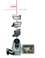
Page 160: ...5 26 ELURA20 MC A ELURA10 A Accessory Section PLUG TYPE DU 300 A JPN E B AS CA 400 BP 406 412 422 2 4 1 SDC 8M WL D75 76 6 7 5 3 ...

Page 161: ...2 D82 0642 000 000 C 1 CORD AC A 3 DY1 8383 000 000 C 1 CARD SD SDC 8M ELURA20 MC A 4 D82 0660 000 000 C 1 DOCKING UNIT DU 300 5 D83 0562 000 000 C 1 WL D75A WIRELESS CONTROLLER ELURA20 MC A D83 0572 000 000 C 1 WL D76A WIRELESS CONTROLLER ELURA10 A 6 DY1 8121 000 000 C 1 COVER BATTERY 7 DY1 8119 000 000 C 1 LABEL WIRELESS CONTROLLER A ...

Page 162: ... VS1 6674 006 000 C 1 CONNECTOR 6P CN1402 VS1 6640 031 000 C 1 CONNECTOR 31P CN1501 VS1 6640 021 000 C 1 CONNECTOR 21P CN1502 VS1 6640 027 000 C 1 CONNECTOR 27P CN3201 VS1 6307 014 000 C 1 CONNECTOR 14P CN3202 VS1 6640 027 000 C 1 CONNECTOR 27P CN3401 WS1 5879 000 000 C 1 CONNECTOR DV FU3201 WD1 5062 000 000 D 1 FUSE FU3202 WD1 5062 000 000 D 1 FUSE JC WS1 5524 000 000 C 1 JACK A V SW WC4 5155 000...

Page 163: ...COVER LM GEAR 21 DA2 0703 000 000 C 1 EJECT LEVER 21 DA2 0712 000 000 C 1 SPRING COIL 23 DA2 0747 000 000 C 1 GUIDE RAIL 19 DA2 0757 000 000 F 1 SCREW 19 DA2 0758 000 000 C 1 SPRING PLATE 23 DA2 0774 000 000 C 2 POST RING RUBBER 23 DA2 0780 000 000 F 2 SCREW 23 DA2 0781 000 000 F 2 WASHER 21 DA2 0782 000 000 F 1 WASHER 19 DA2 0793 000 000 C 1 PLATE TAPE GUIDE 11 DA2 0832 000 000 C 1 HOLDER MULTI 5...

Page 164: ...0 C 1 LITHIUM TERMINAL 9 DA2 0978 000 000 C 1 HOLDER LITHIUM 7 DA2 0980 000 000 B 1 COVER CARD ELURA20 MC A 7 DA2 0981 000 000 B 1 COVER CARD ELURA10 A 7 DA2 0986 000 000 B 1 LABEL CAUTION NEW 9 DA2 0990 000 000 B 1 LABEL LITHIUM 1 7 DA2 0991 000 000 B 1 LABEL LITHIUM 2 7 DA2 0993 000 000 C 1 SHEET MMC 7 DA2 0994 000 000 B 1 HOLDER GRIP BELT 11 DA2 0997 000 000 C 1 SHEET MIC FPC 5 DA2 1007 000 000...

Page 165: ... ASS Y 25 DF1 1516 000 000 C 1 GEAR CAM 1 23 DF1 1517 000 000 C 1 PLATE DRIVE GEAR 25 DF1 1518 000 000 C 1 LEVER ASS Y MODE 25 DF1 1520 000 000 C 1 LEVER ASS Y PR CONTROL 25 DF1 1522 000 000 C 1 LEVER SLIDE 25 DF1 1525 000 000 C 1 GEAR ASS Y TRANS 23 DF1 1544 000 000 C 1 T GUIDE ROLLER ASS Y 23 DF1 1545 000 000 C 2 SKATE ASS Y 23 DF1 1546 000 000 C 1 ARM ASS Y S 23 DF1 1547 000 000 C 1 ARM ASS Y T...

Page 166: ...Y CVF MAIN 11 DH2 2182 000 000 C 1 FPC ASS Y HA SHIELD 5 DH2 2183 000 000 C 1 FPC BATTERY 7 DH2 4055 000 000 C 1 FPC MMC MAIN 21 DH9 0812 000 000 C 1 TAPE DETECTION SW ASS Y 1 13 DH9 0831 000 000 C 1 LCD ASS Y 15 DH9 0836 000 000 C 1 FILTER IR 21 DS1 0169 000 000 C 1 SPRING COIL 21 DS1 0172 000 000 C 1 SPRING COIL 21 DS1 0173 000 000 C 1 SPRING COIL 23 DS1 0174 000 000 C 1 SPRING COIL 21 DS1 0175 ...

Page 167: ... F 1 SCREW 5 XA1 7200 457 000 F 2 SCREW 7 XA4 9140 287 000 F 1 SCREW 17 XA4 9170 309 000 F 1 SCREW 17 XA4 9170 357 000 F 1 SCREW 3 13 XA4 9170 359 000 F 2 SCREW 15 XA4 9170 407 000 F 5 SCREW 13 XA4 9170 409 000 F 2 SCREW 5 XA4 9170 457 000 F 1 SCREW 15 XA4 9170 609 000 F 2 SCREW 5 7 XA9 1000 000 000 F 4 SCREW 3 7 11 XA9 1001 000 000 F 7 SCREW 7 XA9 1002 000 000 F 2 SCREW 7 9 XA9 1004 000 000 F 3 S...

Page 168: ...CHAPTER 6 BLOCK DIAGRAMS CONTENTS INTERCONNECTION DIAGRAM BLOCK DIAGRAMS CAMERA SECTION 1 CAMERA SECTION 2 SYSCON SECTION SERVO SECTION AUDIO SECTION VIDEO SECTION LCD SECTION ...

Page 169: ...801 CN802 AUDIO P C B R KEY UNIT MAIN P C B BATTERY TERMINAL LCD P C B HALL IC BACK LIGHT LCD JACK FPC CCD P C B CA P C B CVF P C B LCD 1 1 1 2 27 26 6 26 CN903 CN901 WP4201 WP4202 CN902 1 8 CN1 REMOTE MIC DUCKING UNIT 1 1 1 2 16 2 21 20 1 2 19 20 1 10 1 1 28 14 15 8 IC1601 PITCH SENSOR CN302 IC300 MOTOR DRIVE IC1601 YAW SENSOR RU01 RECEIVER REMOTE CONTROLLER SUB P C B 50 33 1 11 1 1 5 1 10 51 2 1...

Page 170: ...9 30 31 32 33 34 35 36 37 38 39 40 41 42 43 44 45 46 47 48 49 50 51 MIC1 MIC2 C IN MIC3 GND REC PRF TR C TR LED A TR LED K TR E W W COIL COM GND SENS COM DPG DFG V V U U LOAD LOAD NC GND DEW W W V V SR LED K SR LED A SR C SR E GND CFG2 GND CFG1 CFG VCC BOT E B EOT C EOT E MSW SENS MSW VCC MSW VSS LED K LED A GND W W H U U GND H V V U U DEW GND GND MIC ON MIC3 MIC2 MIC1 LMO CONT UNLOAD LOAD DVDD 3V...

Page 171: ...T4B 17 OUT1A 2 IE2 IE1 OFFSET2 A3V D3V LD SCK D1 8 9 12 13 14 10 4 5 OFFSET 6 DRIVE 7 OUT1B 23 OUT2A 4 OUT2B ZOOM B ZOOM A ZOOM A ZOOM B FOCUS A FOCUS A FOCUS B FOCUS B 21 SUB V2A V3A V4 H1 V1 V2B V3B H2 RG SHD SHP PB OBP DUMC DVDD 15 AVDD 31 AVDD 41 AVDD 38 DVDD 46 CAM 4 7V 15V CAM3V 7 5V CAM 4 7V CAM 3V 15V CAM 3V 7 5V D0 D1 D2 D3 D4 D9 XAGC CS SDO D6 D7 SCK CLK 36M D8 D5 DSPCLK TG NP SEL XTG SE...

Page 172: ... A0 151 CHV A1 152 CHV A2 153 CHV A3 154 CHV A4 155 CHV A5 157 CHV A6 158 CHV A7 ADATA0 ADATA1 ADATA2 ADATA3 DIC 1 7V 15V 7 5V CARD 3V ADATA4 ADATA5 ADATA6 ADATA7 159 CHV B0 141 CHV B1 142 CHV B2 143 CHV B3 144 CHV B4 145 CHV B5 146 CHV B6 CHV B7 BDATA0 BDATA1 BDATA2 BDATA3 BDATA4 BDATA5 BDATA6 BDATA7 147 148 MC DT 118 MC CMO MC CLK 117 116 VDD1 1 VDD3 21 VDD4 40 VDD5 54 VDD6 66 VDD7 67 VDD9 82 VD...

Page 173: ...PE END A D 191 TAPE TOP A D 190 T REEL FG 189 S REEL FG 186 KEY AD2 59 PAE GREEN SW 58 START STOP 91 MAIN EEPROM CS 92 OSDC EEPROM DA SCK 93 OSDC EEPROM DA SO 94 SOUT1 X OUT 121 191 174 PWMD DVDD 3V AVDD 2 3V VCC VCC VCC DIF 3V PWMC 151 RFGT 172 RFGS T REEL FG S REEL FG 153 DFG 130 DPG 132 CFG 1 2 3 1 2 3 X IN 123 CAM PW ON 184 KEY AD0 185 KEY AD1 DIAL CCW DIAL CW EXECUTE 187 KEY AD3 65 DIAL CCW S...

Page 174: ...V V 46 45 42 43 W W 10 11 7 6 2 RU01 3 H 37 CFG2 LOD LOD 38 61 5 63 CFG1 VCC POW 5V H IN OUT VTR UNREG PG AMP CN11 CN14 MO 5V PAE GREEN 4 START STOP SW 5 FOCUS 10 EXP 9 MO 5V 3 LI 3V 6 CAM PW LED 1 VTR PW LED 2 CN13 MAIN SW 0 4 MAIN SW 1 1 MAIN SW 2 2 PAE GREEN 13 START STP SW 14 CN93 CN91 TO DOCKING UNIT LANC DC 16 LANC OUT 15 LANC DC 2 LANC OUT 1 AD KEY 2 18 MO 5V 20 LI 3V 24 LI 3V 25 CAM PW LED...

Page 175: ...14 Q815 Q856 REF REF EXT EXT EXT INT INT INT EXT INT ON ON OFF WIND CUT OFF WIND CUT PB ALC OFF ALC OFF MIC MIC LINE LINE REC REC PB MASTER CLOCK 6 12 7 11 8 9 DE EMP0 18 DE EMP1 17 3 15 10 SERIAL I O D A 19 20 A 3V DVDD 4 7V A D 6 5 7 2 3 1 A M CLK VTR UNREG VTR UNREG SP SP A MUTE SHUTTER 1 BEEP 2 BEEP 1 BEEP LEVEL AIF CS S CLK 2 S OUT 2 A EMP 2 A EMP 1 XPD DA AUD O AUD I EXT CONT LRCK WCK XPD AD...

Page 176: ...C201 1 4 EEPROM FROM SS SECTION MAIN P C B R OUT G OUT B OUT CG MIX BRIGHT TIMING GENERATOR CONTRAST LPF CHROMA REF BLK HCK1 HCK2 HST RGT TST9 FNB TST17 VCK VST SCLK1 EVFSEN SOUT1 SCLK1 SIN1 SOUT1 EVF SEN EVF DA LOAD MAIN EEP CS LCD CEN LCD EEP CS OSDC CS SCK OSD R OSD G OSD B SEN SDAT LCD 3V Q1507 Q1501 Q1508 CLAMP LOGIC Q1503 MO 5V Q1502 R R Y R G Y B B Y G B R G B CN1502 TO LCD CVF SECTION LCD ...

Page 177: ...SOUT1 8 LCD EEP CS 10 LCD CEN 11 SIN1 CLK SO E CS L CS CLK SO CS BRIGHT R OUT G OUT B OUT G CLAMP AGC GCA GCA B CLK CONTROL CSYNC D1 PD PLL ADJ LCD UNREG LCD 3V LCD UNREG OSC O OSC I VC CPCD VDD1 VDD2 VCC1 VSY I XSTH SHT CKH 2 CKH 1 PCG 2 PCG 1 XSTV STV CKV 2 CKV 1 KENB ENB CSYO CSHO XSTH SHT CKH 2 CKH 1 PCG 2 PCG 1 XSTV STV CKV 2 CKV 1 KENB ENB CSYO CSHO E CS CLK SO SO CEN SI 9 COM ADJ 17 PLL ADJ...

Reviews: