background image

197

Displaying the Status Screens

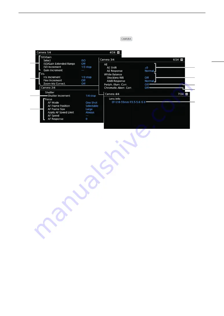
[Camera 1/4] to [Camera 4/4] Status Screens 

(


mode  only)

7

5

8

3

1

2

9

4

6

1

ISO speed/Gain (

A

69) 

Selected mode, extended range, ISO increment 
and gain increment

2

Aperture  (

A

72) 

Iris increment, aperture correction while zooming

3

Shutter speed increment (

A

68) 

4

Focus  (

A

80)

AF mode, AF frame settings, AF speed and AF 
response settings

5

Automatic exposure (AE)
AE shift (

A

75), AE response (

A

74)

6

White balance (

A

77)

Shockless white balance, auto white balance 
(AWB) response

7

Correction for peripheral illumination (

A

39)

8

Correction for chromatic aberration (

A

39)

9

Lens model name info (

A

37)

Summary of Contents for C200B

Page 1: ...Digital Cinema Camera Instruction Manual Firmware ver 1 0 5 1 00 PUB DIE 0504 000F...

Page 2: ...ademark of Oracle Corporation its affiliates or subsidiaries in the United States and other countries HDMI the HDMI logo and High Definition Multimedia Interface are trademarks or registered trademark...

Page 3: ...depth Both MP4 and XF AVC clips can be recorded in 3840x2160 or 1920x1080 and in 8 bit color depth For details on available combinations of frame size frame rate and color depth see the video configu...

Page 4: ...sh to use Then you can adjust a number of other image related parameters in detail Other Functions Save XF AVC clips with ease Use the XF Utility software A 158 to save XF AVC clips to a computer The...

Page 5: ...44 Attaching the Shoulder Strap 44 Removing and Attaching the Terminal Covers 45 Using the Optional EVF V70 Electronic Viewfinder 46 Preparing Recording Media 47 Compatible Recording Media 47 Inserti...

Page 6: ...nce Signal 105 Color Bars 105 Audio Reference Signal 105 Waveform Monitor 106 Displaying the Waveform Monitor 106 Configuring the Waveform Monitor 106 Adding Marks to Recordings 108 Adding a Shot Mark...

Page 7: ...minal device and HDR setting 155 Superimposing Onscreen Displays on Screens Video Outputs 156 Audio Output 157 Working with Clips on a Computer 158 Saving MP4 Clips 158 Saving XF AVC Clips 158 Develop...

Page 8: ...8...

Page 9: ...in this manual Screen refers to the LCD screen on the LCD monitor1 and to the viewfinder2 screen on the camera SD card refers to an SD SDHC or SDXC memory card Recording media refers to CFast cards an...

Page 10: ...e Camera On and Off A 27 and Selecting the Main Recording Format A 64 The arrow is used to abbreviate steps in procedures For a detailed explanation on how to use the menus refer to Using the Menus A...

Page 11: ...tly from the accessories supplied with the lens kit LM V1 LCD Monitor1 LA V1 LCD Attachment Unit1 UN 5 Unit Cable1 HDU 2 Handle Unit1 Microphone Holder incl M4 fixation bolts x 2 GR V1 Camera Grip1 2...

Page 12: ...Q switch A 27 8 CFast card slot cover 9 CFast card slot A 48 10 Card release button for CFast card slot A 48 11 ISO GAIN button A 69 Assignable button Camera 5 A 125 12 SHUTTER shutter speed mode butt...

Page 13: ...e optional RC V100 Remote Controller or commercially available remote controllers 10 HDMI OUT terminal A 149 153 11 Screw holes for the microphone holder fixation bolts 12 MIC microphone terminal A 98...

Page 14: ...automatic aperture button A 74 Assignable button Camera 10 A 125 4 Built in monaural microphone A 103 5 EF lens mount index A 37 6 EF S lens mount index A 37 7 Lens release button A 37 8 EF lens lock...

Page 15: ...STATUS display Audio status screen button A 199 Assignable button Camera 9 A 125 11 Audio level switches for CH1 top and CH2 bottom A 101 12 Audio level dials for CH1 top and CH2 bottom A 101 13 SD ca...

Page 16: ...3 Strap mounts A 44 4 Screw holes for 1 4 20 mounting screws 8 5 mm 0 33 in deep 5 Screw hole for 3 8 16 mounting screws 10 mm 0 39 in deep A 42 6 TB 1 Tripod Base 7 Tripod socket for tripods with 0 9...

Page 17: ...n Monitor 2 A 125 8 mark for aligning the LCD monitor s position A 28 9 Screw hole for 1 4 20 screws 11 2 mm 0 44 in deep 10 VIDEO terminal A 28 10 9 12 11 13 1 2 3 4 5 7 8 6 1 LCD attachment unit bas...

Page 18: ...accessory for the C200B 1 4 5 6 7 8 9 10 2 3 1 Control dial A 70 72 2 REC start stop recording button A 56 3 Grip belt A 44 4 Joystick A 33 SET button A 33 5 FOCUS GUIDE button A 82 Assignable button...

Page 19: ...in total on the handle unit 2 Front accessory mount2 Includes a screw hole for 1 4 20 screws 8 8 mm 0 35 in deep 3 Top accessory shoe 4 Through holes 8 8 mm 0 35 in 5 Rear accessory mount Includes a s...

Page 20: ...mary clip is XF AVC format proxy clip recording is not available After recording on a CFast card develop the CFast card data using the Cinema RAW Development software A 159 to generate full quality da...

Page 21: ...to ACES2065 1 color space Output Transform Refers to the table used for mapping ACES2065 1 color space information to the specific color information scheme used by the display device ASC CDL Refers t...

Page 22: ...4K Workflow Overview 22...

Page 23: ...ck 1 Connect the power cord to the CA CP200B Compact Power Adapter For North America Make sure you use the power cord for the CA CP200B See the sidebar below for information on differentiating the sup...

Page 24: ...s refer to the Reference Tables A 230 For approximate recording times with a fully charged battery pack refer to the Specifications A 226 Charged battery packs continue to discharge naturally Therefor...

Page 25: ...rt the battery pack all the way into the compartment as shown in the illustration and press it gently toward the left until it clicks Removing the Battery Pack 1 Set the Q switch to OFF 2 Holding down...

Page 26: ...the camera is powered using a power outlet you can replace the battery pack even when the camera is turned on North America only The power cord for the CA A10 AC Adapter is different from that for the...

Page 27: ...plug it into a power outlet IMPORTANT Make sure to turn off the camera before connecting or disconnecting the AC adapter When using the AC adapter do not fix it permanently to one place as this may c...

Page 28: ...t Unit1 to the LM V1 LCD Monitor1 you can attach the LCD monitor to the HDU 2 Handle Unit1 or directly to the camera body itself For details on adjusting the LCD monitor refer to Using the LCD Monitor...

Page 29: ...cable clamp If necessary adjust the position of the cable so that it does not get in the way of the lens NOTES Depending on the situation the screws may become loose If necessary use the hex wrench f...

Page 30: ...nal to the LCD monitor s VIDEO terminal 2 Supplied accessory for the C200 optional accessory for the C200B Align the marks on the cables plugs and terminals Removing the LCD Monitor and LCD Attachment...

Page 31: ...Universal Time UTC 2 Change the rest of the fields in the same way 3 Select Set and then press the joystick to start the clock and close the screen NOTES You can display the date time in mode with the...

Page 32: ...hat some settings and screens will be displayed in English regardless of the language setting 1 Press the MENU button 2 Push the joystick up down to select B System Setup and then press the joystick 3...

Page 33: ...me indicating the menu item that was selected the previous time the menu was closed unless the camera was turned off 2 Push the joystick left right to select the desired submenu To select a different...

Page 34: ...p down left right SET buttons in the same way as the camera s joystick Pressing the SET button is equivalent to pressing the joystick on the camera You can check most of the current settings on the st...

Page 35: ...s on a different page Select the page that corresponds to the desired set 2 Select OK and then press the joystick twice Renaming the Selected My Menu Set You can give each of the 5 My Menu sets a more...

Page 36: ...r modular units when attaching removing or adjusting the various accessories Use a table or other stable surface to change the camera s configuration NOTES Compatibility with the optional SU 15 Should...

Page 37: ...ea Place the body cap back on the lens mount and the dust caps on the lens Clean any dust or dirt from the body cap and dust caps before using them Attaching an EF Lens 1 Set the Q switch to OFF 2 Rem...

Page 38: ...on website and save it on an SD card Insert the SD card containing the lens firmware update into SD card slot B 2 Attach the lens you wish to update to the camera and open the lens firmware submenu B...

Page 39: ...area that is used for producing the image 1 Open the EF S Lens submenu Camera Setup EF S Lens 2 Select On and then press the joystick will appear at the lower center of the screen When EF S Lens is s...

Page 40: ...y horizontally or vertically the camera s onscreen displays will be turned off You can use the B System Setup Touch Screen Response setting to adjust the LCD monitor s response to touch input k Using...

Page 41: ...e setting and then press the joystick When the viewfinder is turned off the menu items will appear grayed out 3 Select the desired level and then press the joystick Repeat steps 2 and 3 to adjust othe...

Page 42: ...then press the joystick Using a Tripod The camera is shipped with the TB 1 Tripod Base When mounting the camera on a tripod with 0 95 cm 3 8 mounting screws use the tripod socket for tripods with 0 95...

Page 43: ...lose it 4 Screw the thumb rest onto the camera Attaching the Camera Grip The camera grip can be attached in a number of positions from 90 toward the lens to 60 toward the viewfinder at 6 intervals 1...

Page 44: ...h the microphone holder to the LCD attachment unit You can also attach the microphone holder to the camera directly 2 Use a commercially available Phillips head crosshead screwdriver to secure it firm...

Page 45: ...inals to access them more easily Removing the Terminal Covers Open the terminal cover and gently pull it straight out Attaching the Terminal Covers Insert the connecting strip into the opening to atta...

Page 46: ...also be output to the EVF V70 1 Supplied accessory for the C200 optional accessory for the C200B 1 Attach the handle unit A 28 2 Set the Q switch to OFF 3 Perform the steps up to but not including att...

Page 47: ...D cards 3 To record XF AVC clips we recommend using SD cards rated Speed Class 10 or UHS Speed Class 1 or 3 To record 4K clips 3840x2160 or clips using slow motion recording mode we recommend using SD...

Page 48: ...until the CFast card access indicator is off or is illuminated in green 2 Slide the CFast card slot cover switch in the direction of the arrow The CFast card slot cover will open 3 Make sure the CFas...

Page 49: ...serve the following precautions while an SD card access indicator is illuminated in red Failure to do so may result in permanent data loss Do not disconnect the power source or turn off the camera Do...

Page 50: ...tion may take up to a few minutes NOTES While recording on an SD card you can initialize another SD card in the other SD card slot If you set an assignable button to Initialize Media A 125 you can pre...

Page 51: ...ding 2 Select On and then press the joystick 4 appears at the top of the screen NOTES Relay recording the switch to the other SD card will not be performed during slow motion recording even if the rec...

Page 52: ...ress the joystick 4 Select OK and then press the joystick The camera will attempt to recover the corrupted data 5 When the confirmation message appears press the joystick NOTES In the RAW clip or MP4...

Page 53: ...rame rate 4 When the confirmation message appears press the joystick If the sensor is not completely shielded from light Error will appear on the screen Press the joystick and repeat the procedure fro...

Page 54: ...Adjusting the Black Balance 54...

Page 55: ...g operation You can also include metadata with the clip Preparing to Record 1 Attach the LCD monitor handle unit camera grip etc as necessary to build the desired configuration A 36 2 Attach a charged...

Page 56: ...while an access indicator is illuminated in red Failure to do so may result in permanent data loss Do not open the card slot cover of the card being accessed and do not remove the card Do not disconne...

Page 57: ...physical controls buttons and switches on the camera save for the REC button This is useful in preventing settings from being changed due to inadvertently pressing one of the buttons Return the Q swit...

Page 58: ...selected for recording is indicated with a mark in red No SD card or cannot record on the SD card r Recording format A 64 0000 mm Approximate focal length of the lens 1 Focal Length Focus mode A 80 1...

Page 59: ...STBY PRE REC Pre recording A 115 record standby recording STBY 6 CONT STBY 7 REC 6 CONT REC 7 Continuous recording A 118 both cards in record standby both cards recording The upper row 6 indicates the...

Page 60: ...indicated accurately 2 Remaining Battery Icon Display Description Custom Display 00 00 00 00 User bit A 95 2 User Bit A001C001 to Z999D999 Clip identification Includes the camera index reel number an...

Page 61: ...new card Continuous Clip numbers will start from the initial number set with Clip Number following procedure and continue across multiple cards Operating modes A 0 0 1 C 0 0 1 _ y y m m d d X X _ C A...

Page 62: ...Numbering submenu Recording Media Setup MP4 Clip Photo Numbering 2 Select the desired option and then press the joystick Options Reset MP4 clip photo numbers will restart from 100 0001 every time you...

Page 63: ...stick Options Automatic The fan runs while the camera is not recording and is automatically turned off while the camera is recording However if the internal temperature of the camera is too high b app...

Page 64: ...control in how the final picture turns out XF AVC clips deliver high quality video due to efficient compression MP4 clips have a smaller file size and are very versatile 1 Please note that the Cinema...

Page 65: ...compress the image after analyzing also changes across a group of pictures and offer better compression smaller data size NOTES NOTES For details on the signal output from each terminal refer to Video...

Page 66: ...ed will be highlighted in orange Press the FUNC button repeatedly or push the joystick left right to select the function you wish to adjust 2 Push the joystick up down to select the desired value ISO...

Page 67: ...a standard shutter speed based on the frame rate Available Shutter Speeds The available shutter speeds vary depending on the system frequency and frame rate used 1 59 94i and 50 00i are available onl...

Page 68: ...nding on the shutter speed You may be able to avoid flicker by setting the shutter speed mode to Speed and the shutter speed to a value matching the frequency of the local electrical system 1 50 or 1...

Page 69: ...elect ISO or Gain and then press the joystick 3 Open the ISO Increment or Gain Increment submenu to select the adjustment increment to use when adjusting the ISO speed or gain respectively v Camera Se...

Page 70: ...gain perform the previous procedure A 69 Turn the control dial assigned to ISO Gain to set the desired ISO speed or gain value NOTES NOTES When high ISO speeds or gain levels are set the picture may...

Page 71: ...Only when v Camera Setup Extended ND Range is set to On NOTES NOTES If you set an assignable button to ND or ND A 125 you can press the button to change the ND filter setting Depending on the scene t...

Page 72: ...perture from the camera you will need to enable automatic adjustment using the controls on the lens Required settings vary depending on the lens Refer to the following table and the instruction manual...

Page 73: ...utton to Iris or Iris A 125 you can press the button to respectively open up the aperture smaller F values or close it larger F vales When using an EF lens with no lens contacts or most EF Cinema lens...

Page 74: ...n recording Automatic Aperture When a compatible EF lens is attached to the camera you can have the camera automatically adjust the aperture 1 Open the aperture Iris Mode submenu v Camera Setup Iris M...

Page 75: ...posure bar and the camera will attempt to adjust the exposure accordingly NOTES NOTES If you set an assignable button to AE Shift or AE Shift A 125 you can press the button to adjust the AE shift leve...

Page 76: ...the joystick The icon of the selected mode or appears on the left of the screen Options Backlight Suitable when recording backlit scenes Standard Averages the light metered from the entire screen givi...

Page 77: ...white balance to the optimal level NOTES NOTES The White Balance and Color Matrix Tuning settings in the custom picture file A 136 take precedence over the white balance set with these procedures You...

Page 78: ...ce 1 Press the WB button The white balance mode icon will be highlighted in orange You can also use the FUNC button and joystick to enter the direct setting mode 2 Push the joystick up down to select...

Page 79: ...en next to the white balance icon NOTES NOTES Custom white balance may provide better results in the following cases Changing lighting conditions Close ups Subjects in a single color sky sea or forest...

Page 80: ...ture while keeping the focus on the selected spot Face AF1 The camera automatically detects a person s face focuses on it and can track it if that person moves Tracking1 After you select a subject the...

Page 81: ...uch the subject if the focus guide is not displayed For details on using the focus guide refer to Dual Pixel Focus Guide A 82 1 Supplied accessory for the C200 optional accessory for the C200B 5 Turn...

Page 82: ...25 Alternatively you can use the A Assistance Functions Focus Guide setting to turn the focus guide on and off 2 If necessary use the joystick to move around the focus frame When using the LCD monitor...

Page 83: ...your finger across the screen to move the frame Press the CANCEL button to return the magnification frame to the center position 3 Press the MAGN button again to cancel the magnification 1 If one of t...

Page 84: ...ou release the ONE SHOT AF button NOTES NOTES One shot AF will not work in the following cases When slow motion recording is activated When the shutter speed mode is set to Slow and the shutter speed...

Page 85: ...may take longer in the following cases When the frame rate set in the video configuration is set to 29 97P 25 00P 24 00P or 23 98P With some EF lenses the camera may take longer to focus automatically...

Page 86: ...he camera s system frequency is changed If the lens is removed or replaced If v Camera Setup AF Mode is changed to One Shot If the camera is set to slow motion recording mode When the digital tele con...

Page 87: ...he joystick left right or touch the desired subject on the LCD screen to change the main subject when there is more than one person During continuous AF the camera will keep focusing on the main subje...

Page 88: ...you will need to set an assignable button to Tracking in advance 1 Set an assignable button to Tracking A 125 2 Press the assignable button The subject selection mark I will appear on the screen Pres...

Page 89: ...Camera Grip Zoom Speed 5 Select the desired zoom speed and then press the joystick Zoom speeds are constant 1 being the slowest and 16 the fastest 6 Close the menu and use the joystick on the camera g...

Page 90: ...Markers SDI HDMI Output select On and then press the joystick Select Markers VF VIDEO Output l Markers VIDEO Output to display the markers on the viewfinder k only and from the VIDEO terminal select M...

Page 91: ...ge and then press the joystick NOTES NOTES You can turn off all other onscreen displays leaving only the onscreen markers A 60 Markers are not available when the video output from the HDMI OUT termina...

Page 92: ...ptions Preset The time code starts from an initial value you can select in advance The default initial time code is 00 00 00 00 See the following procedures to select the time code running mode and se...

Page 93: ...Drop or Non Drop Frame When the frame rate is set to 59 94P 59 94i or 29 97P you can select between a drop frame DF or non drop frame NDF time code depending on how you plan to use your recordings Wi...

Page 94: ...be changed When you are using interval recording frame recording or slow motion recording the time code signal will not be output from the SDI terminal or HDMI OUT terminal When you mix drop frame and...

Page 95: ...own identification code Time to use the time as the user bit or Date to use the date as the user bit If you selected Time or Date the rest of the procedure is not necessary If you selected Setting co...

Page 96: ...so be output with the video signal from the SDI terminal and HDMI OUT terminal You can record this audio signal on an external recorder 1 Available for MP4 clips only 2 Only for recording notes while...

Page 97: ...nal digital audio INPUT Terminals INPUT Terminals ANALOG AES EBU INPUT 2 INPUT 1 terminal INPUT 2 terminal digital audio INPUT Terminals INPUT Terminals ANALOG ANALOG INPUT 2 INPUT 1 terminal INPUT 2...

Page 98: ...ne holder you can fix external microphones with a diameter of 19 mm to 20 mm Follow the procedure below to attach a microphone refer also to the following illustration To connect an external device to...

Page 99: ...ANT When connecting an analog microphone or device that does not support phantom power make sure to set the corresponding INPUT switch to MIC or LINE respectively If you set the switch to MIC 48V the...

Page 100: ...For information on the monaural microphone see About the monaural microphone A 103 Recording a Single Analog Audio Input to Two Audio Channels By default when using analog audio sources line in or mi...

Page 101: ...el s audio level Manual Audio Level Adjustment for CH1 or CH2 You can set the audio level for each channel manually from to 18 dB 1 Set the audio level switch of the desired channel to M manual 2 Turn...

Page 102: ...the amplitude of audio input signals when they start to distort Use the Audio Setup INPUT 1 2 Limiter setting We recommend using headphones when adjusting the audio level If the input level is too hig...

Page 103: ...et to MIC Terminal 1 Open the MIC Att submenu Audio Setup MIC Att 2 Select On and then press the joystick Activating the Low Cut Filter MIC Terminal You can activate the low cut filter for example to...

Page 104: ...hone terminal to monitor the recorded audio NOTES NOTES You can adjust the headphone volume with the Audio Setup 1 Headphone Volume setting If you set an assignable button to Headphones or Headphones...

Page 105: ...ate the color bars 3 Open the Color Bar Type submenu v Camera Setup Color Bar Type 4 Select the type of color bars and then press the joystick NOTES NOTES If you set an assignable button to Color Bars...

Page 106: ...coordinate open the WFM Select Line submenu A Assistance Functions WFM Select Line 4 Push the joystick up down to select the first digit of the Y coordinate and then press the joystick to move to the...

Page 107: ...EO terminal or from the SDI terminal with the A Assistance Functions WFM VF VIDEO Output l WFM VIDEO Output or WFM SDI Output settings The waveform monitor will not be affected even if a LUT is applie...

Page 108: ...lay from when you press the button to when the camera adds the shot mark When a clip contains a shot mark will appear next to the clip s thumbnail in the playback index screen Shot marks cannot be add...

Page 109: ...data Setting submenu 3 Recording Media Setup Metadata Setting 4 Select SD Card and then press the joystick 5 Open the User Memo submenu 3 Recording Media Setup Metadata User Memo 6 Select the file nam...

Page 110: ...identify the recording later on 1 Open the Scene or Take submenu 3 Recording Media Setup Metadata Scene or Take 2 Select Change and then press the joystick Enter the desired text using the keyboard s...

Page 111: ...in places where the use of electronic devices is restricted The recorded GPS information may contain data that can lead others to locate or identify you Be careful when sharing geotagged recordings w...

Page 112: ...conds backward or forward respectively When there are less than 10 seconds from the start of the clip pushing the joystick left will start playing back the clip from the beginning When there are less...

Page 113: ...remove the card Do not disconnect the power source or turn off the camera NOTES NOTES If the recording of the primary clip stops during simultaneous recording recording of the proxy clip will stop as...

Page 114: ...ogressive frame rate shooting frame rate that is different from the playback frame rate Recording a clip at a higher frame rate than the Frame Rate setting will result in a slow motion effect during p...

Page 115: ...When the special recording mode is deactivated the time code running mode will return to its previous setting Pre recording Mode When pre recording mode is activated the camera starts recording contin...

Page 116: ...FRM STBY changes to FRM REC while recording frames and FRM STBY when frames are not being recorded Repeat until you finish recording 2 When you have finished recording turn off the special recording...

Page 117: ...of the recorded frames are joined together into one clip The tally lamp goes out and INT STBY appears at the top of the screen with INT flashing 3 When you have finished recording turn off the special...

Page 118: ...3 Select Continuous Recording and then press the joystick The continuous recording mode is activated and CONT STBY 7 appears at the top of the screen The normal recording indicator changes to STBY 6...

Page 119: ...al recording mode at a time When continuous recording mode is activated if recording on SD card B continuous recording is not available normal recording on SD card A will not be possible either When c...

Page 120: ...ng precautions while the SD CARD 3 access indicator is illuminated in red Failure to do so may result in permanent data loss Do not disconnect the power source or turn off the camera Do not remove the...

Page 121: ...red photo 2 Press the button to view the photo The photo playback screen appears and the selected photo is displayed Push the joystick left right to switch to the previous next photo Press the DISP bu...

Page 122: ...1 or open the Photos index screen and move the orange selection frame to the desired photo 2 Press the joystick to open the photo menu 3 Select Delete and then press the joystick The screen prompts yo...

Page 123: ...camera and open the REMOTE Term submenu B System Setup REMOTE Term 3 Select RC V100 REMOTE A and then press SET Options RC V100 REMOTE A Select this option to use the optional RC V100 Remote Controlle...

Page 124: ...Using the Optional RC V100 Remote Controller 124...

Page 125: ...ffers 4 additional assignable buttons that can be used when they are each connected to the camera In most cases the names of the buttons printed on the camera and modular units also indicate their def...

Page 126: ...efer to the following table for assignable functions and available modes Function name Description A One Shot AF 1 The camera focuses automatically one time only one shot AF function 84 AF Lock Locks...

Page 127: ...e balance setting 77 AWB Lock While using auto white balance AWB locks the current white balance settings 79 AWB Set A Set B Daylight Tungsten Kelvin Changes the white balance mode setting to the resp...

Page 128: ...the direct setting mode with the shutter speed highlighted and ready to be adjusted 68 ISO Gain Enters the direct setting mode with the ISO speed or gain value highlighted and ready to be adjusted 69...

Page 129: ...y the file to the camera in advance A 132 When you close the menu the selected custom picture file s settings will be applied The icon of the Gamma setting in effect will appear on the left of the scr...

Page 130: ...tom picture file copy it in advance to an SD card or select in advance a custom picture file you do not mind changing Editing a Custom Picture File s Settings 1 Select a custom picture file A 129 2 Op...

Page 131: ...g Custom Picture Files Protecting a custom picture file prevents its settings from being accidentally changed 1 Select a custom picture file A 129 2 Open the Protect submenu Custom Picture HDR File Pr...

Page 132: ...wish to replace A 129 2 Open the Load from SD Card B submenu Custom Picture HDR File Load from SD Card B 3 Select the file with the settings that you want to replicate and then press the joystick 4 Se...

Page 133: ...e Normal 1 Standard setting Normal 3 BT 709 Setting suitable for playback on TV monitors Produces a more faithful black gradation in the shadows dark areas of the image than with the Normal 2 x4 0 set...

Page 134: ...e Point 20 to 50 0 These settings control the lower part of the gamma curve dark areas of the image When Gamma is set to one of the Canon Log settings or Wide DR these settings are not available Level...

Page 135: ...of coring adjustment in other words how the coring level changes from the value set for Coring Level to that set for Coring D Ofst level dependent curve HV Detail Bal 8 to 8 0 Adjusts the ratio betwe...

Page 136: ...nce R Gain B Gain 50 to 50 0 These settings adjust the amount of white balance throughout the whole image by changing the intensity of red tones R gain and blue tones B Gain Color Matrix Tuning Gain 5...

Page 137: ...Camera Settings 1 Open the Load submenu B System Setup Transfer Menu Load 2 Select From Camera or From SD Card B and then press the joystick 3 Select OK and press the joystick The camera s menu setti...

Page 138: ...Saving and Loading Camera Settings 138...

Page 139: ...is MP4 or XF AVC clips are saved on an SD card If the recording media contains clips recorded at a system frequency other than the one currently used by the camera you will not be able to play back t...

Page 140: ...ou press the button on the clip index screen the index screen selection menu will appear 2 Select the desired index screen and then press the joystick The selected index screen appears Select Cancel i...

Page 141: ...op the playback and return to the index screen IMPORTANT Observe the following precautions while an access indicator is illuminated in red Failure to do so may result in permanent data loss Do not dis...

Page 142: ...3 Shutter speed1 A 67 4 Joystick guide A 143 5 Recording media 6 7 SD card CFast card 6 Playback operation 7 Frame rate A 64 For clips recorded using slow motion recording the shooting frame rate and...

Page 143: ...e headphone terminal to listen to the audio during playback Adjust the headphone volume with the Audio Setup Speaker Volume or Headphone Volume setting If you set an assignable button to Headphones or...

Page 144: ...er action may be required Follow the onscreen directions Press the CANCEL button instead to return to the clip index screen IMPORTANT Observe the following precautions while an access indicator is ill...

Page 145: ...custom picture file recorded with it push the joystick down to display the first of four screens with the clip s custom picture settings Data 1 4 screen Push the joystick down to display the other th...

Page 146: ...Mark from the Index Screen 1 Open the XF AVC index screen select the desired clip and then press the joystick to open the clip menu 2 Select Add Mark or Add Mark and then press the joystick The clip...

Page 147: ...t mark Deleting All Shot Marks in a Clip from the Index Screen 1 Select the desired clip and then press the joystick to open the clip menu 2 Select Del All Shot Marks and then press the joystick The c...

Page 148: ...en the clip menu 2 Select Delete User Memo and then press the joystick The Delete User Memo screen appears and it prompts you to confirm the operation 3 Select OK and then press the joystick The user...

Page 149: ...x21604 1920x10804 RAW 59 94P 29 97P 23 98P 4096x2160 2048x1080 YCbCr 4 2 2 10 bit 1920x10805 YCbCr 4 2 2 10 bit 59 94i 29 97PsF6 1920x10805 YCbCr 4 2 2 10 bit 1920x10805 YCbCr 4 2 2 10 bit 59 94i 1920...

Page 150: ...YCbCr 4 2 2 8 bit 60 00i 1920x1080 YCbCr 4 2 2 8 bit Operating modes Clip s video configuration Video output configuration Video format1 Frame rate2 Resolution SDI terminal3 HDMI OUT terminal3 SDI ou...

Page 151: ...YCbCr 4 2 2 8 bit 59 94i 29 97PsF6 1920x10805 YCbCr 4 2 2 8 bit 3840x2160 YCbCr 4 2 2 8 bit8 1920x1080 YCbCr 4 2 2 8 bit 59 94i 1920x10805 YCbCr 4 2 2 8 bit 1920x1080 1920x10805 YCbCr 4 2 2 8 bit 720...

Page 152: ...nal up to 4 channels and the recording command signal When using the SDI terminal you can output various assistance displays onscreen markers magnification onscreen displays in order to check them als...

Page 153: ...e external recorder You can set Recording Media Setup Rec Command to On to use the camera s REC button to control also the recording operation of an external recorder connected to the SDI terminal How...

Page 154: ...der connected to the HDMI OUT terminal The camera s time code signal will be output as well The time code will not be output from the HDMI OUT terminal in the following cases During mode During SD out...

Page 155: ...2 Push the joystick up down to select the desired output device or terminal 3 Press the joystick 4 Push the joystick left right to select the desired LUT Available options depend on the output device...

Page 156: ...OSD Output 2 Select On and then press the joystick T appears on the right of the screen only if 1 Monitoring Setup Custom Display 2 OSD Output is set to On 1 l Appears on the previous page in the menu...

Page 157: ...toring Setup 1 Custom Display 2 Monitor Channels is set to On 1 l Appears on the previous page in the menu Options All of the following settings are available for Monitor Channels only CH1 CH2 and CH3...

Page 158: ...ins the software Saving XF AVC Clips You can use Canon XF Utility to save and organize XF AVC clips on a computer and the Canon XF plugins to easily use the clips directly from major non linear editin...

Page 159: ...DF file included in the compressed file you will download from the website For details about using the software refer to the instruction manual PDF file that is installed with the software Cinema RAW...

Page 160: ...Working with Clips on a Computer 160...

Page 161: ...ion or settings Additionally Canon shall not be liable for any loss or damage caused by the use of network functions Using an unprotected Wi Fi network can expose your data to monitoring by unauthoriz...

Page 162: ...een the camera and supported Wi Fi enabled devices The functionality is not the same as that of commercially available access points Infrastructure connection WPS button If your wireless router suppor...

Page 163: ...cryption skip to step 8 If you selected WPA2 PSK AES continue with step 7 7 Enter the password of the access point Enter the desired text using the keyboard screen A 35 This encryption key password is...

Page 164: ...stick to save the network configuration 4 When the confirmation screen appears press the joystick Connecting in Infrastructure Mode 1 Open the connection method selection submenu Network Settings Conn...

Page 165: ...ddress assignment A 163 NOTES The WPS Button method may not work correctly if there are several active access points in the area In such case try using WPS PIN Code or Search for Access Points A 166 i...

Page 166: ...r active access points in the vicinity and display a list of available options on the screen 2 Push the joystick up down to select the desired access point and then press the joystick 3 If necessary s...

Page 167: ...tication method is Open you can select WEP and continue to step 4 or No Encryption and skip to step 6 If the authentication method is WPA PSK or WPA2 PSK you can select TKIP or AES 4 If necessary sele...

Page 168: ...ailable Ethernet cable to the Ethernet terminal on the camera and an Ethernet port on a network device 2 Open the connection method selection submenu Network Settings Connection Settings select the de...

Page 169: ...le even after the initial setup Changing settings manually requires more advanced knowledge of Wi Fi and network settings 1 Open the configuration profile selection submenu Network Settings Connection...

Page 170: ...case of a multi camera shooting setup Changing the Port Number and Camera ID 1 Open the Browser Remote Settings submenu Network Settings Browser Remote Settings 2 To change the port number select Por...

Page 171: ...nections connect the camera to the desired network using an Ethernet cable and the connection type icon will appear at the top of the screen When the icons turn white the camera is ready to accept com...

Page 172: ...off in an endless loop The camera s ID and lens information will appear on the Browser Remote screen while live view is not activated 5 Select the language for Browser Remote Click touch the language...

Page 173: ...data screen and a basic screen that allows users only to start stop recording using a smartphone or other device with a small screen The screen displayed will differ depending on the user information...

Page 174: ...remote recording screen to open the metadata screen A 179 or to open the basic screen for devices with a small screen A 181 7 Language selection Most of the application s controls emulate physical bu...

Page 175: ...the monitoring live view screen and touch Use the same lighting conditions you plan to use when recording During the procedure the icon in the button will flash quickly When it stops flashing the pro...

Page 176: ...erture value will appear as a T value During manual aperture adjustment you can also touch PUSH AUTO IRIS to have the camera adjust the aperture automatically once The manual aperture buttons will not...

Page 177: ...s Guide function button 7 ONE SHOT AF button A 177 AF Lock button A 178 8 Tracking buttons 9 Manual focus buttons Manual focus 1 Touch the AF mode button and select One Shot 2 Touch one of the manual...

Page 178: ...ocus at its current position and frame the picture as necessary Touch the button again to release the AF lock When the focus is locked with AF lock you can focus manually Touching the screen to focus...

Page 179: ...adjust the zoom The zoom can be adjusted only when an EF Cinema lens compatible with zoom adjustment or an EF lens compatible with the optional PZ E1 Power Zoom Adapter is attached to the camera 1 Se...

Page 180: ...nstead Touch Clear All to delete all the GPS related fields at once 3 Live view screen Shows the camera s live view image When the live view image is not turned on the camera ID and lens information w...

Page 181: ...The metadata sent to the camera from Browser Remote will be lost in the following cases If the camera was turned off If the 3 Recording Media Setup Metadata Setting setting was changed Using Browser R...

Page 182: ...keyboard screen A 35 5 Select whether to activate the passive mode Passive Mode On or Off Press the joystick Off is the standard setting for most cases On passive mode is more appropriate for FTP tra...

Page 183: ...en the confirmation message appears press the joystick Transferring Multiple Clips 1 Open the desired index screen A 140 2 Connect the camcorder to the desired network A 169 Use an Infrastructure conn...

Page 184: ...remain at the transfer destination Do not open the SD card slot cover Do not remove the power source or turn off the camera If incomplete files remain at the transfer destination check the content and...

Page 185: ...A 189 A Assistance Functions menu A 190 7 Network Settings menu A 192 Assignable Buttons menu A 192 B System Setup menu A 193 My Menu customized menu A 194 Menu item Setting options and additional inf...

Page 186: ...oom Speed 1 to 16 8 A 89 Tele converter 6 0x 3 0x 1 5x Off The digital tele converter allows you to digitally increase the focal length of the camera by the selected multiplier Note that the image is...

Page 187: ...BY A 118 Frame Rate When System Frequency is set to 59 94 Hz 59 94i 59 94P 29 97P 23 98P When System Frequency is set to 50 00 Hz 50 00i 50 00P 25 00P XF AVC clips only A 64 Resolution Color Sampling...

Page 188: ...Photo Numbering Reset Continuous A 62 Menu item Setting options and additional information Select CH1 CH2 Input INPUT Terminals MIC Terminal Monaural Mic A 100 CH2 Input INPUT 2 INPUT 1 A 100 Select...

Page 189: ...e EVF V70 s contrast EVF V70 Color 20 to 20 0 Adjusts the EVF V70 s color EVF V70 Sharpness 1 to 4 2 Adjusts the EVF V70 s sharpness EVF V70 Luminance High Normal Adjusts the EVF V70 s luminance EVF V...

Page 190: ...OSD Output Rec Command User Memo User Bit Monitor Channels Audio Level Indicator Network Functions GPS On Off On Normal Show the icon onscreen display always or whenever the necessary conditions are t...

Page 191: ...Line 1 When the vertical resolution is 1080 0 to 1079 540 in 1 line increments Set When the vertical resolution is 2160 0 to 2158 1080 in 2 line increments Set A 106 k Markers VF VIDEO Output l Marker...

Page 192: ...Password Meta Password Password up to 8 characters 12345678 FTP Transfer Select All FTP Transfer Settings A 182 FTP Server Server name up to 32 characters FTP User Name User name up to 32 characters F...

Page 193: ...DI Output 2048x1080 1920x1080 1920x1080 A 152 3G SDI Mapping Level A Level B A 153 SDI HDMI Scan Mode P PsF A 154 Time Code Mode Preset Regen A 92 Time Code Run Rec Run Free Run A 92 Time Code DF NDF...

Page 194: ...atic Always On Fan Speed Always High Low Touch Screen Response 5 Normal Low A 40 Review Recording Entire Clip Last 4 sec A 112 GPS Auto Time On Off A 111 Retract Lens 1 On Off When one of the followin...

Page 195: ...ace Color Matrix screen A 195 Data screens A 196 Camera screens A 197 Assignable Buttons screens A 198 Audio screens A 199 Media screen A 200 Terminal Outputs screen A 200 Recording screen A 201 Metad...

Page 196: ...6 Knee settings slope point and saturation A 134 7 Sharpness settings level horizontal detail frequency horizontal vertical detail balance limit and select A 135 8 Coring settings level offset and cu...

Page 197: ...Iris increment aperture correction while zooming 3 Shutter speed increment A 68 4 Focus A 80 AF mode AF frame settings AF speed and AF response settings 5 Automatic exposure AE AE shift A 75 AE respon...

Page 198: ...reens Current functions of the assignable buttons A 125 1 Supplied accessory for the C200 optional accessory for the C200B 4 2 3 1 5 1 On the camera s body 2 On the camera grip1 3 On the LCD monitor1...

Page 199: ...input audio level adjustment mode and audio level indicator for each audio channel A 96 2 Audio channels output from the headphones speaker A 157 3 Headphone volume A 143 4 Audio format A 96 audio bit...

Page 200: ...e only 6 5 7 1 2 3 4 8 9 1 SD card A 2 SD card B 3 CFast card For each 4 Visual bar Approximate used available space 5 Total space 6 Used recorded space 7 Available space Only for the SD card 8 Number...

Page 201: ...for interval recording mode A 117 6 MP4 Clip Photo numbering A 62 7 Clip numbering A 61 2 1 3 4 5 6 9 7 8 1 User memo file name A 109 2 Clip title 3 Camera operator 4 Filming location 5 Clip descripti...

Page 202: ...creens 202 Battery Hour Meter Status Screen 1 2 3 4 5 1 Remaining recording time 2 Remaining recording time indicator 3 Battery life indicator 4 Total operation time A 194 5 Operation time since using...

Page 203: ...163 6 1 2 3 4 5 13 10 11 12 7 8 9 1 Network configuration name A 169 2 Connection type 3 SSID network name 4 Authentication and encryption method 5 WEP index key 6 Wi Fi frequency band and channel 7 I...

Page 204: ...password itself will not be displayed 2 1 3 4 1 Camera ID 2 Port number 3 Camera s URL 4 User setting A 170 user name and password settings 5 1 2 3 4 6 7 8 FTP server settings A 182 1 FTP server host...

Page 205: ...GPS Information Display Status Screen mode only For details refer to Recording GPS Information Geotagging A 111 1 2 3 4 5 1 Latitude 2 Longitude 3 Elevation 4 UTC coordinated universal time date and...

Page 206: ...lready contains the maximum number of clips 999 clips Delete some clips A 147 or save your clips A 158 and initialize the recording media A 50 to free some space Alternatively replace the recording me...

Page 207: ...is set to prevent accidental erasure Change the position of the LOCK switch Photos that were protected using other devices cannot be deleted with the camera Indicators and Onscreen Displays appears in...

Page 208: ...ge the battery pack Remove the battery pack and reattach it correctly Abnormal characters appear on the screen and the camera does not operate properly Disconnect the power source and reconnect it aft...

Page 209: ...o RC V100 REMOTE A when using the optional RC V100 Remote Controller or Standard when using a commercially available remote control Turn off the camera reconnect the remote controller and then turn th...

Page 210: ...problem refer to Precautions Regarding Wi Fi Networks A 211 When you reset all the camera settings all network settings are lost as well Set up the Camera Access Point settings again A 163 Cannot con...

Page 211: ...is section appear in alphabetical order Note that for some messages an indication of the recording media involved SD card A SD card B CFast or a combination thereof may appear above the message itself...

Page 212: ...at the frame rate selected on the camera Select a different the frame rate A 64 Lens error Turn the camera off then on again There was a communication error between the camera and the lens Turn the c...

Page 213: ...ull so recording will continue on the other SD card in approximately 1 minute Some clips require data recovery While recording the camera s power stopped or the memory card was removed causing an erro...

Page 214: ...works access points in the area but none were found Make sure the access point is working correctly and try connecting again The access point is operating in stealth mode Deactivate the stealth functi...

Page 215: ...ces in the network including the camera are configured with the correct gateway address Wi Fi connection terminated An error occurred on the access point or connected device Check the network or conne...

Page 216: ...attery packs If a battery battery pack leaks and the material contacts your skin or clothing flush the exposed area thoroughly with running water In case of eye contact flush thoroughly with copious a...

Page 217: ...Do not use or store the camera in dusty or sandy places The camera is not waterproof avoid also water mud or salt If any of the above should get into the camera it may damage the camera and or the len...

Page 218: ...ged and uncharged battery packs For example with charged battery packs attach the terminal cover so that the shaped hole shows the colored label Remaining battery time If the remaining battery time di...

Page 219: ...ored data is not physically erased Take the necessary precautions when you dispose of the recording media for example by physically damaging it to prevent the leakage of private data If giving the rec...

Page 220: ...ed Continued use may damage the camera Condensation may form in the following cases When the camera is moved quickly from cold to warm places When the camera is left in a humid room When a cold room i...

Page 221: ...1 Camera Grip HDU 2 Handle Unit EVF V70 OLED Electronic Viewfinder RD 1 Rod Clamp RC V100 Remote Controller CL V2 Clamp Base TB 1 Tripod Adapter Base CG A20 Battery Charger and CA CP200B Compact Power...

Page 222: ...s mount For details consult the retail dealer from whom you purchased the camera or contact a Canon Service Center Use of genuine Canon accessories is recommended The message Battery communication err...

Page 223: ...clips RAW Bit rate 1 Gbps Resolution 4096x2160 Color depth 10 bit or 12 bit depending on the frame rate Frame rate 59 94P 50 00P 29 97P 23 98P 25 00P 24 00P MP4 Bit rate 150 Mbps 35 Mbps Resolution 3...

Page 224: ...Speed 1 3 stop increments 1 4 stop increments angle clear scan slow off Iris Manual 1 2 stop increments 1 3 stop increments fine tuning push auto iris automatic aperture ISO Speed ISO 1004 ISO 1254 I...

Page 225: ...tal displays superimposed onscreen displays magnification can also be output INPUT Terminals INPUT 1 and INPUT 2 XLR 3 pin jack pin1 shield pin2 hot pin3 cold 2 sets balanced Analog Inputs Sensitivity...

Page 226: ...169 x 209 x 137 mm 6 7 x 8 2 x 5 4 in 1 All dimensions are approximate Weight2 k Camera unit only 1430 g 3 2 lb Camera with handle unit LCD monitor LCD attachment unit camera grip microphone holder e...

Page 227: ...75 mm 5 6 x 4 6 x 3 0 in Weight Approx 255 g 9 0 oz GR V1 Camera Grip Modular unit can be attached at any of 24 positions 6 intervals includes limited recording controls Dimensions W x H x D 60 x 124...

Page 228: ...AC Rated Output 24 V DC 1 8 A Operating Temperature 0 40 C 32 104 F Dimensions W x H x D 67 5 x 37 x 134 mm 2 7 x 1 5 x 5 3 in Weight Approx 290 g 10 2 oz BP A30 Battery Pack Battery Type Rechargeabl...

Page 229: ...nses CN20x50 IAS H E1 CN7x17 KAS S E1 CN E18 80mm T4 4 L IS KAS S CN E70 200mm T4 4 L IS KAS S Prime lenses compatible with Dual Pixel Focus Guide Lens Focus control from the camera Focus guide Manual...

Page 230: ...The charging times given in the following table are approximate and vary according to charging conditions and initial charge of the battery pack Bit rate CFast card capacity 1 Gbps 64 GB 5 min 128 GB...

Page 231: ...Compatible CFast cards 47 Initializing 50 Inserting Removing 48 Recording method 51 Check marks 108 146 Cinema RAW Development 159 Clips Adding an mark mark 108 146 Adding Deleting shot marks 108 147...

Page 232: ...tick guide 143 K Key lock 57 L Language 32 LCD attachment unit1 28 LCD monitor1 28 LCD screen 41 Lens 37 Lens correction chromatic aberration peripheral illumination 39 Lens firmware 38 Light metering...

Page 233: ...92 S Safe area 90 Saving clips to a computer 158 Saving XF AVC clips 158 SD card Compatible SD cards 47 Initializing 50 Inserting Removing 49 Search for access points 166 Shooting frame rate 114 Shot...

Page 234: ...ited Warranty covers all defects encountered in normal use of the Products and does not apply in the following cases A Loss or damage to the Products due to abuse mishandling accident improper mainten...

Page 235: ...d in normal use of the Products and does not apply in the following cases A Loss or damage to the Products due to abuse mishandling accident improper maintenance use of non Canon accessories or failur...

Page 236: ...ion USA http pro usa canon com CANON U S A INC http pro usa canon com support 855 CINE EOS 855 246 3367 USA only UNITED KINGDOM Canon UK Ltd Unit 160 Centennial Park Centennial Avenue Elstree Hertford...

Reviews: