32
Bouton
d’embrayage
Interrupteur
du moteur à 3
positions
Fonctionnement de votre treuil à
ligne lestée
Après avoir installé le treuil à ligne lestée Cannon
sur votre bateau, relâchez une longueur de ligne de
votre canne à pêche et enroulez-la pour que le leurre
se trouve à distance de 1,5 à 30 m (5 à 100 pi) du
bateau. Ceci s’appelle une retombée.
Attachez la ligne à pêche fermement dans le
déclencheur de ligne. Appuyez et gardez l’interrupteur
à levier vers le bas pour baisser le poids à la
profondeur voulue qui figure sur le profondimètre.
Placez la canne à pêche dans le support et embobinez
la section lâche pour que votre canne à pêche
présente une légère courbure. Lorsqu’un poisson
mordra à l’hameçon, la ligne se séparera du
déclencheur. Vous serez alors libre de manipuler votre
canne à pêche pour capturer le poisson.
Descente du poids
Le Mag 20 DT peut descendre le poids de la
pêche à la traîne en mode manuel ou automatique.
Descente manuelle : rapide ou lente
En tournant le bouton d’embrayage lentement
dans le sens horaire (vers le bras), vous pouvez faire
descendre le poids de la pêche à la traîne aussi
rapidement ou lentement que vous voulez. Si vous
tournez le bouton dans le sens antihoraire (loin du
bras) le poids s’arrêtera. Vous pouvez ainsi décider de
laisser le poids descendre rapidement ou lentement à
une profondeur de la pêche à la traîne prédéterminée.
Avec plusieurs treuils, vous pouvez faire descendre
tous les poids lentement, un à la fois, et ensuite les
arrêter chacun à leur tour.
Descente automatique
Gardez l’interrupteur à levier vers le bas jusqu’à ce
que le poids atteigne la profondeur désirée et relâchez.
Le moteur s’arrêtera lorsque l’interrupteur est relâché
ou mis en position neutre.
Interrupteur du
moteur à 3
positions
Pour baisser le
poids
Fonctionnem
ent
de votre tre
uil à
ligne
lestée
Pour lever le
poids
9
CAUTION: This rod holder is intended for use
of up to 30 lb. test line only, and is not
recommended for use with any tackle IGFA
rated higher than 30 lb. A safety strap (not
included) is recommended for all
applications.
The rod holder assembly is not warranted
when used with tackle above 30 lbs.
Equipment placed in the rod holders and the
loss thereof is the responsibility of the user
and is in no way warranted by JOHNSON
OUTDOORS, INC. Mounting must be in
accordance with the above instructions and
diagram to be warranted.
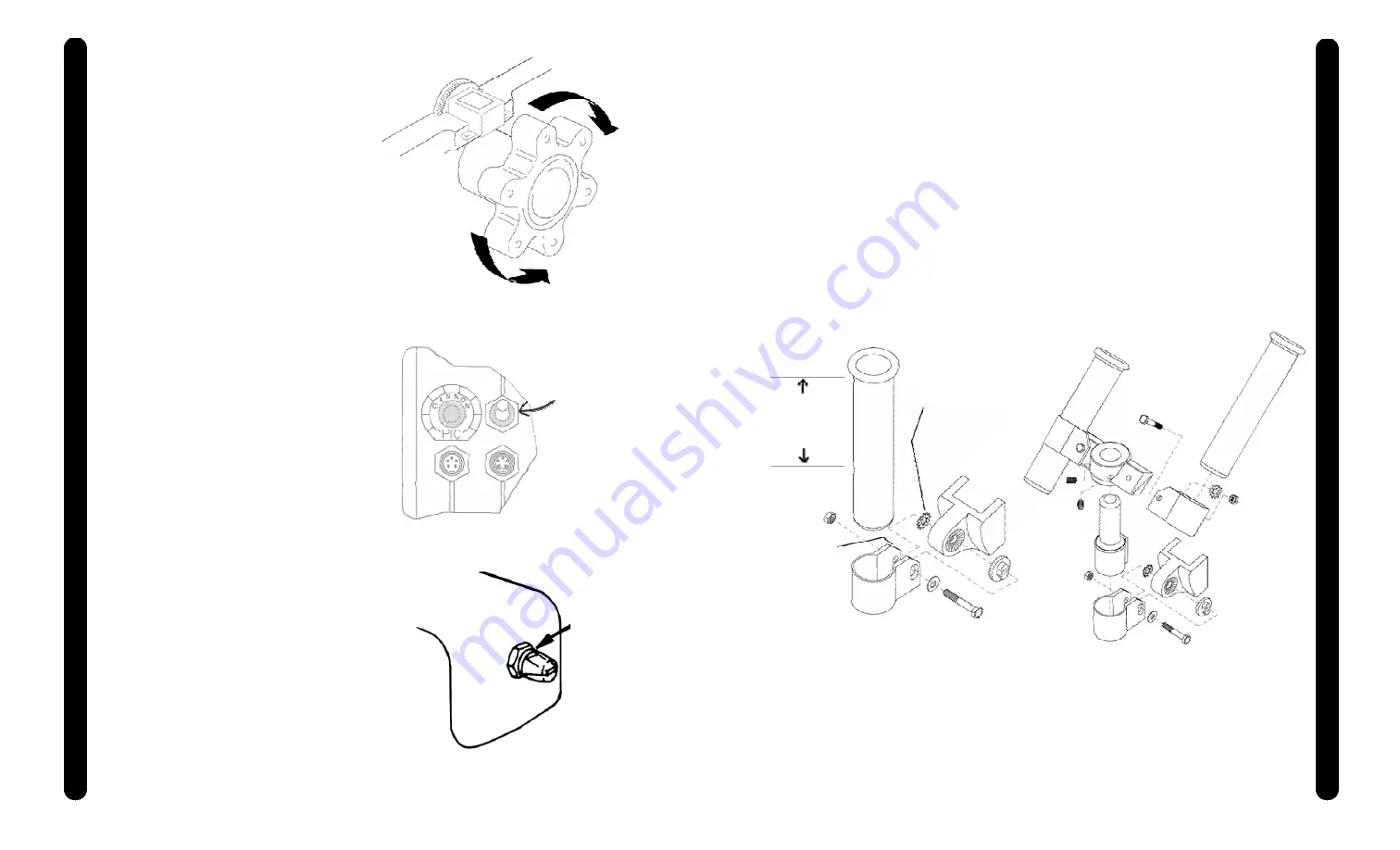
Attaching the Rod Holder
The positive lock rod holder incorporates a
locking disk that allows the rod holder to be
aligned in 15 degree increments. Slide the rod
holder tube into the clamp to the desired position
within the recommended area (see below). Be
sure the angled shoulders are facing up. Place
the locking disk into the mating recess of the
frame. Slip the clamp arms in place where the
obround tab on the disk fits into the slot on the
clamp. Slide the star washer between the arm of
the clamp and the frame. Place the flat washer
onto the bolt. Then insert the bolt with washer
through the clamp by entering the disk, going
through the frame, the star washer, and out the
other side of the clamp. Tighten the nut to
secure the rod holder. Reposition the rod holder
by loosening the nut and adjusting the tilt.
Single Rod Holder Assembly
Star Washer
Placement
Angled
Shoulder
Recommended
Area to Clamp
Rod Holder
Dual Rod Holder Assembly
ATTA
CHING THE
ROD HOLDE
R


