18
There is a unique burner for each model. Burners may not be
interchanged between different input models.
4.8
– Ignition System
4.8.1
– Hot Surface Igniter (Glow Bar)
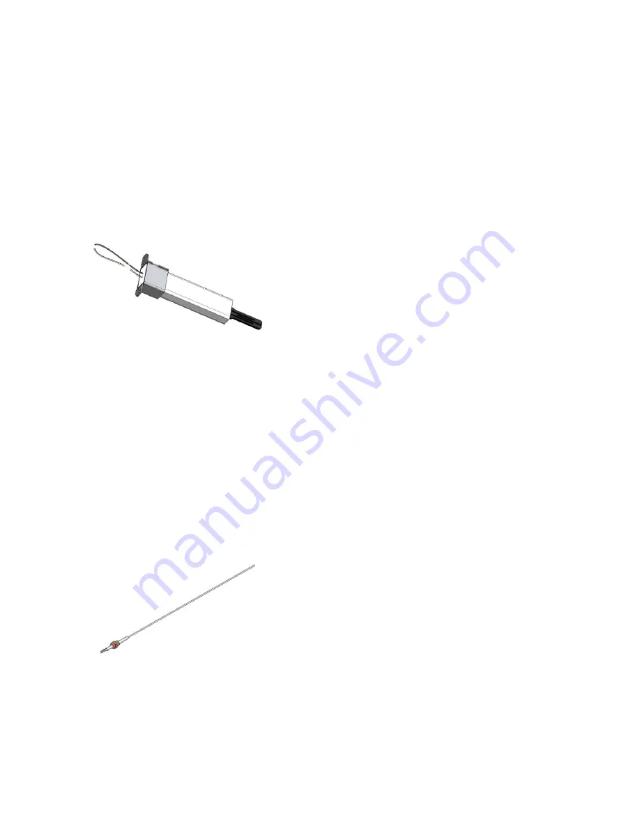
The silicon carbide igniter is inserted directly through the fan
flange and held in place by two screws. A hold down bracket as
well as sealing gasket above and below the igniter assures a
good seal. Care must be taken when removing and/or installing
the igniter since the silicon carbide element is brittle. Always
remove the igniter prior to removing the fan assembly for
inspection of the burner and Tank. A properly prepared igniter
will have a bead of silicone sealing the end mounting bracket to
the ceramic shaft.
Hot Surface Igniter
During trial for ignition a properly operating igniter will generate a
minimum 3.2+/-0.2A which is the current required for reliable
ignition. Direct ignition is standard. The burner mounting flange
provides a flame view port and the mounting point for the hot
surface igniter and the flame sensor.
The hot surface igniter and flame sensor are removable from
the burner mounting flange without removing the burner
assembly from the heat exchanger.
4.8.2
– Flame Sensor
The flame sensor is inserted directly through the fan flange and
is screwed into the fan flange. Care must be taken when installing
the flame sensor to align it perpendicular to the fan flange and
parallel to the burner tube and not to over tighten. Always remove
the flame sensor prior to removing the fan assembly for
inspection of the burner and heat exchanger.
Flame Sensor
The ignition module relies on the flame sensor to provide a flame
rectification signal. Oxide deposits, improper placement or
damaged ceramic insulator will result in insufficient signal leading
to ignition module lock out. For proper operation minimum 0.8
Vdc must be fed back to the module. Oxide deposit on the sensor
rod must be removed with steel-wool. Do not use sand-paper
since this will contaminate the surface.


