


31
Part 8 – Commissioning/Start-up
8.1
– Checking the Installation
Inspect the water, gas and electrical connections. Confirm they
are all in compliance with the instructions in this manual. Verify
gas pressure is within the ranges listed in Table 4 before
proceeding. Confirm that all gas connections to the heater are
tight, and that there are no leaks or missing test plugs.
Repair
any leaks and replace plugs before proceeding.
All units are test fired and factory set. A test sticker with
actual reading is affixed to the unit.
Check the wiring to see that it agrees with the wiring diagram
supplied. Confirm that all terminal strips and field connections are
identified. Confirm that the VTech controller is set in the proper
mode. Auto reset limits are fixed in all modes.
The coldest water temperature possible must be used when
setting up low fire combustion. Cold temperatures cause flue
products to condense, resulting in large amounts of condensate
build up on the stainless steel heat transfer tubes, which in turn
creates the highest back pressure through the unit. At minimum
input this creates the most critical combustion setup point. It is
recommended to perform setup under these conditions quickly,
to ensure low temperatures are maintained throughout the
commissioning, for single or multiple appliance installations.
8.2
– Checking Gas Supply Pressure
Turn the main power switch to “OFF” position.
Shut off gas supply at the manual gas cock in the gas piping
to the appliance. If fuel supply is LP gas, shut off gas supply
at the tank.
Remove the 1/8" hex plug from the gas pressure test port
located on the inlet gas supply connection at the rear of the
appliance. Install a fitting in the inlet pressure tapping suitable
to connect to a manometer (or magnahelic gauge). Range of
scale should be 0 to 14 inch WC or greater.
Turn on gas supply at the field installed manual gas cock; turn
on LP gas at tank if required.
Ensure inlet pressure is within specified range. Minimum and
maximum gas supply pressures are specified in Table 4.
IMPORTANT
If gas pressure is out of range, contact the gas utility, gas
supplier, qualified installer or service agency to determine
necessary steps to provide proper gas pressure to the control.
Upon completion of any change to the gas system, leak test
all gas connections with a soap solution Immediately repair
any leak found in the gas train or related components. DO
NOT operate an appliance with a leak in the gas train, valves
or related gas piping.
Do not attempt to fire the unit with insufficient gas supply
pressure. Never use an open flame (match, lighter, etc.)
to check gas connections.
Turn the power switch to “ON” position. If filled with cold water
the tank should automatically observe a demand to heat the
water. Verify target temperature is higher than current water
temperature.
Once safety checks are complete, the control will run through
the ignition cycle. It is normal during initial startup, when air
is being purged from the piping, to require several attempts
before successful ignition. This may require clearing a lockout
for failed ignition.
Continued ignition failures may indicate
a problem with the gas supply.
When ignition is successful and the unit is in operation, check
for flue gas leaks along the inner cabinet joints and around
the flue outlet. If any leaks are found, deactivate the unit and
repair immediately.
Unit should modulate to 100% of rated input, observe the gas
supply pressure at this level. Ensure that gas pressure
remains stable within the ranges listed in Table 4. The inlet
gas pressure must not exceed a 30% reduction between
light-off and full fire conditions.
If gas supply pressure is within normal range, proceed adjust
combustion settings, if necessary.
8.3
– Combustion Setup
At the factory adjustments were made to achieve proper input
and acceptable burner performance at full input and at minimum
input. Depending on field conditions, the combustion setup may
require some adjustment. To ensure the coldest possible water
temperatures for set up on multiple water heater systems, the low
fire combustion should be established on all water heaters before
setting any water heater high fire combustion rates.
Table 6: Target Combustion Values
Natural Gas
Propane
CO
2
CO
CO
2
CO
Max. Input
8.5% - 9.0%
<100
PPM
9.5% - 10.0%
<100
PPM
Min. Input
8.0% - 8.5%
<100
PPM
9.0% - 9.5%
<100
PPM
In order to perform adjustments to the gas valve the VTech must
be firing before proceeding, and the gas inlet pressure must
already have been verified.
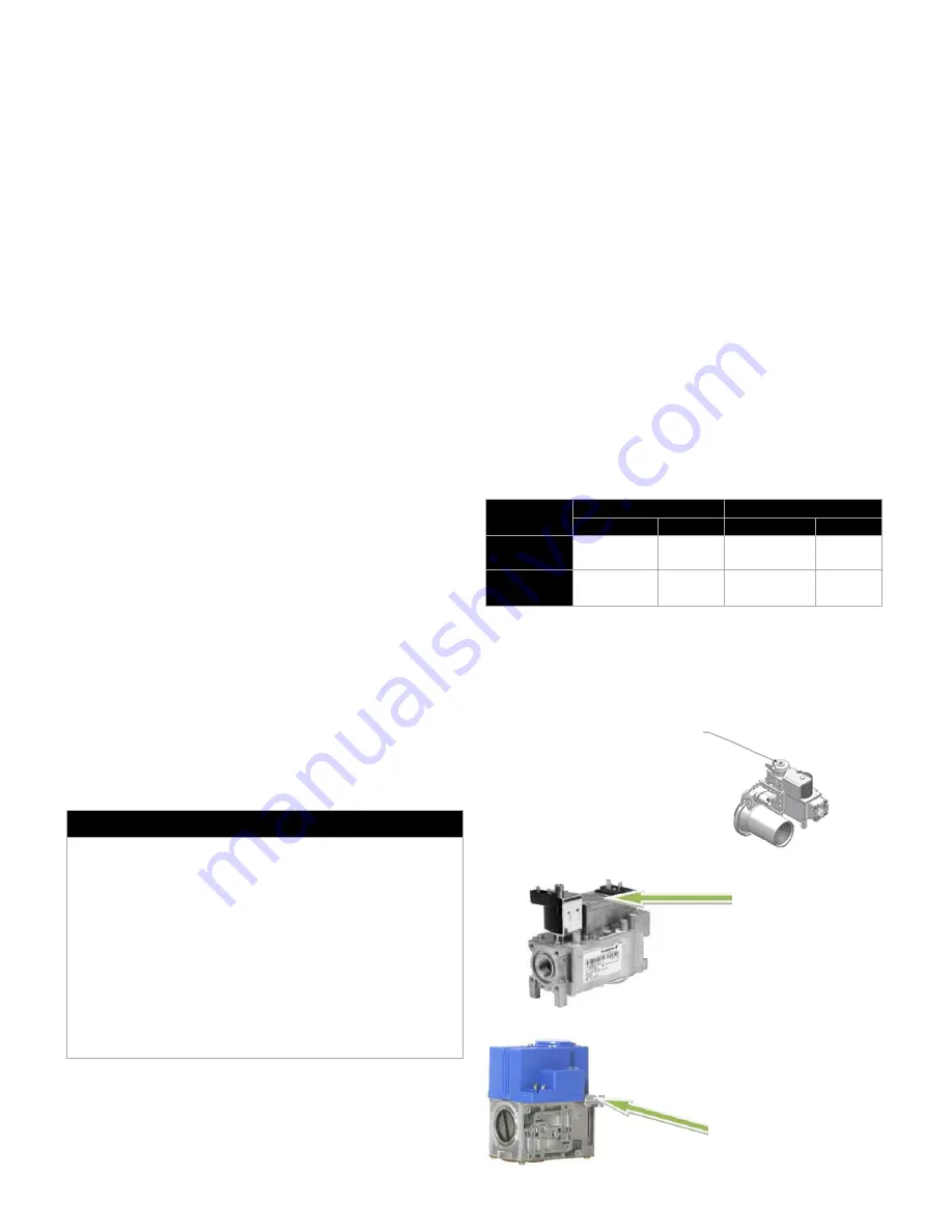
8.3.1
– Adjust Low Fire Setting
VT80 to 250
– Negative Pressure Control Valve
VT299 to VT399
– Negative Pressure Control Valve
VT499
– Negative Pressure Control Valve
Low-fire air gas ratio
adjustment (use Torx 40
for adjustment clockwise
increases CO
2
)
Low-fire air/gas ratio
adjustment, use slotted
screwdriver for adjustment,
clockwise increases CO
2
Low-fire adjustment
screw (use Torx 40 for
adjustment, clockwise
increases CO
2
)