background image

4

Please read the following safety precautions and instructions in their entirety 

before use.

The barbecue model shown in this manual may look different from yours. It is 

for illustration purpose only. 

NOTE: Unless otherwise specified, following generic terms “appliance / unit / product / 

equipment / device” appeared in this instruction manual all refer to the product “Rotisserie Kit”.

A - FOR YOUR SAFETY

•  Read the operating instructions carefully before using the device. Keep the instructions 

in a safe place afterwards so that you can access them whenever required.

•  This appliance can be used by children aged from 8 years and above and 

persons with reduced physical, sensory or mental capabilities or lack of 

experience and knowledge if they have been given supervision or instruction 

concerning use of appliance in a safe way and understand the hazards involved.

• 

Cleaning and user maintenance shall not be made by children without supervision.

• 

Children should be supervised to ensure that they do not play with the appliance.

• 

If the supply cord is damaged, it must be replaced by the manufacturer, its service agent or 

similarly qualified persons in order to avoid a hazard.

• 

Extinguish your barbecue before the following operation.

• 

Wait until your barbecue has cooled down before the following operation.

• 

The rotisserie kit has sharp edges; handle with care and keep out of reach of children.

• 

Protect the electrical outlet from bad weather conditions, particularly from rain.

B - PREPARATION

• 

Remove the warming racks, griddles and grids before installing the rotisserie kit.

• 

Remove packagings, especially the protective cases on the fork tines and the ends of rotisserie rod.

• 

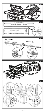
Place the burner tents onto the burners to prevent fat dripping while grilling. (Fig. 1)

C - ASSEMBLY

1.  Rotisserie Rod (Fig. 2)

The rotisserie kit comes with rotisserie rod in three types of lengths, each designed for different 

barbecue models.

a.  Choose the rotisserie rod adapted to your barbecue model.

b.  If needed, screw the optional rod onto the end of the rotisserie rod. (Fig. 2-A)

2.  Forks and Handle (Fig. 3)

a.  Insert a pair of forks onto rotisserie rod, adjust the distance between them as needed. (Fig. 3-A)

b.  To secure both forks on the rod, rotate the levers clockwise until they are hand-tight. (Fig. 3-B)

c.  Screw the handle onto the threaded end of the rotisserie rod. (Fig. 3-C)

3.  Motor Support and Handle Support (Fig. 4, 5 & 6)

There are 2 methods to secure the motor support and handle support to the barbecue, which 

depends on the type of supporting brackets welded on your barbecue frame. For the supporting 

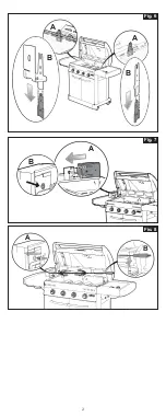
brackets as Fig. 5-A, proceed Method 1; For those as Fig. 6-A, proceed Method 2.


Method 1 - Screws Required (Fig. 4 & 5)

a.  Remove two side walls numbered “3 and 1” if needed, which depends on your barbecue 

model. For the removal of these parts, refer to the assembly manual. (Fig. 4)

b.  Align both screw holes on the handle support to those on the supporting bracket, then 

insert two screws through the holes. (Fig. 5-B)

c.  Place two ear nuts over the ends of the screws, making sure they are centered. Keep the 

upper ear nuts in vertical (Fig. 5-C) and the lower ones in horizontal (Fig. 5-D) so as to 

avoid interference from closing the lid. Use a cross screwdriver to tighten the screws in 

clockwise until they are hand-tight.

d.  Repeat Step b and c to secure the motor support. (Fig. 5)

e.  Reinstall two side walls numbered “3 and 1” if you have taken Step a. For the installation of 

these parts, refer to the assembly manual. (Fig. 4)


Method 2 - Screws Not Required (Fig. 6-B)

a.  Respectively slide down the motor support and the handle support to the supporting brackets.

b.  Make sure the motor support and the handle support are inserted in position.

4.  Attaching the Motor to the Motor Support (Fig. 7)

a.  Slide the motor to attach it to the motor support. (Fig. 7-A)

b.  Make sure the hole on the motor lines up with that on the motor support. (Fig. 7-B)

5.  Placing the Rotisserie Rod on the Barbecue (Fig. 8)

a.  Hold and tilt the rotisserie rod, place the pointed end of the rod onto the motor support so 

as to move the end into the hole on the motor a little bit. (Fig. 8-A)

b.  Lay the other end of the rod onto the handle support, then completely insert the pointed end 

to the hole on the motor. (Fig. 8-B)

D - USE

a.  Check that the forks does not slide or move around after they’ve been secured.

b.  Make sure that the rotisserie rod is appropriately placed on the motor support and the handle support.

c. 

Make sure the food are well fixed on the rod and not in direct contact with the burner tents.

d.  Make sure that the pointed end of the rotisserie rod is completely inserted to the motor.

e.  Plug the motor cable into any standard polarized 230 Volt AC electrical outlet.

f.  To start grilling, switch the button on the motor to “

I

” position.

DO NOT use the side burner while the rotisserie kit is working.

DO NOT leave your rotisserie kit unattended while it is working.

Accessible parts may get hot while grilling. Keep children away.

E - DISASSEMBLY

a.  To stop grilling, switch the button on the motor to “

O

” position.

b.  To disassemble the rotisserie kit, follow the steps given in Section C in the reverse order.

The rotisserie rod and forks may get hot after grilling. Wait until they have cooled down 

before disassembly, or remove them with oven gloves.

F - CLEANING AND STORAGE

• 

Wait until your barbecue has cooled down before cleaning.

• 

Always turn off and unplug the motor before cleaning.

• 

Clean burner tents, rotisserie rod and forks after each grilling, using a damp sponge with 

dish washing liquid. DO NOT use abrasive scrubbers or brushes. If needed, only clean the 

housing of the motor in the same way. NEVER submerge the entire motor in water.

• 

Before storage, the rotisserie kit should be well dried. To avoid injury caused by sharp edges, it 

is recommended to cover the forks tines and the ends of rotisserie rod with protective cases.

• 

When not used for a long period of time, it is recommended the rotisserie kit be stored in a 

dry, sheltered place.

G - ELECTRICAL AND ELECTRONIC WASTE PRODUCTS

This symbol means that the appliance’s electrical system must be disposed of 

selectively. At the end of its life, the appliance’s electrical system must be scrapped 

correctly. The electrical system must not be disposed of with unsorted household 

wastes. Selective collection of waste promotes reuse, recycling or other forms 

of recovery of recyclable materials contained in this waste. Take the appliance’s 

electrical system to a waste recovery centre designed for the purpose (waste 

collection point). Check with your local authorities. Never dispose of in nature, do not 

incinerate: the presence of certain hazardous substances in electrical and electronic equipment 

can be harmful to the environment, and have a potential effect on human health.

GB

Summary of Contents for 82804644

Page 1: ...BETJENINGSVEJLEDNING 13 INSTRUKCJA OBSłUGI 14 NÁVOD NA POUŽITÍ 15 NÁVOD NA POUZITI 16 HASZNÁLATI ÚTMUTATÓ 17 UPORABA IN VZDRŽEVANJE 18 UPORABA I ODRŽAVANJE 19 FOLOSIRE SI ÎNTRETINERE 20 ИНСТРУКЦИИ ЗА УПОТРЕБА 21 KASUTUSJUHEND 22 LIETOĐANAS PAMÂCÎBA 23 NAUDOJIMO INSTRUKCIJA 24 ΟΔΗΓΙΕΣ ΧΡΗΣΗΣ 25 FR GB DE ES PT IT NL NO SE FI DK PL CZ SK HU SI HR RO BG EE LV LT GR APPLICATION DES GAZ 219 Route de Bri...

Page 2: ...1 A 2 Series RBS Master 3 Series 3 Series 3 Series RBS 4 Series Master 4 Series Fig 1 Fig 2 Fig 3 A A C B Fig 4 C D C D B B A A Fig 5 ...

Page 3: ...2 Fig 6 Fig 7 A A B B A B Fig 8 B A ...

Page 4: ...ciforme serrez les vis en sens horaire jusqu à les bloquer manuellement d Reprenez les étapes b et c pour fixer le support du moteur Fig 5 e Si vous avez sélectionné l étape a réinstallez les deux parois latérales numérotées 3 et 1 Pour installer ces pièces voir le manuel de montage Fig 4 Méthode 2 Sans vis Fig 6 B a Faites glisser le support du moteur et le crochet dans les supports de fixation b...

Page 5: ...Repeat Step b and c to secure the motor support Fig 5 e Reinstall two side walls numbered 3 and 1 if you have taken Step a For the installation of these parts refer to the assembly manual Fig 4 Method 2 Screws Not Required Fig 6 B a Respectively slide down the motor support and the handle support to the supporting brackets b Make sure the motor support and the handle support are inserted in positi...

Page 6: ...bb 5 e Installieren Sie die beiden Seitenwände mit den Nummern 3 und 1 erneut wenn Sie Schritt a ausgeführt haben Entnehmen Sie die Einzelheiten der Installation dieser Teile der Montageanleitung Abb 4 Methode 2 Schrauben nicht benötigt Abb 6 B a Schieben Sie den Motorträger und die linke Halterung entsprechend nach unten auf die Stützhalterungen b Stellen Sie sicher dass der Motorträger und die l...

Page 7: ...n firmes d Repita los pasos b y c para fijar el soporte del motor Fig 5 e Vuelva a instalar las dos paredes laterales marcadas con los números 3 y 1 si ha realizado el Paso a Para la instalación de estas partes consulte el manual de ensamblado Fig 4 Método 2 No se necesitan tornillos Fig 6 B a Deslice respectivamente el soporte del motor y el soporte del mango por los soportes de su barbacoa b Ase...

Page 8: ...ssos b e c para prender o suporte do motor Fig 5 e Reinstale as duas paredes laterais numeradas 3 e 1 se tiver seguido o Passo a Para a instalação destas peças consulte o manual de montagem Fig 4 Método 2 Não são Necessários Parafusos Fig 6 B a Deslize respetivamente o suporte do motor e o suporte da pega para as braçadeiras de suporte b Certifique se de que o suporte do motor e o suporte da pega ...

Page 9: ...e d Ripetere i passi b e c per fissare il supporto motore Fig 5 e Reinstallare i due pannelli laterali numerati 3 e 1 se si è eseguito il passo a Per l installazione di questi pannelli consultare il manuale di montaggio Fig 4 Metodo 2 Viti non necessarie Fig 6 B a Far scivolare rispettivamente il supporto del motore e il supporto del manico verso le staffe di supporto b Assicurarsi che il supporto...

Page 10: ...c om de motorsteun te bevestigen Afb 5 e Monteer opnieuw de twee zijpanelen met de nummers 3 en 1 als u stap a heeft uitgevoerd Raadpleeg de montagehandleiding voor het bevestigen van deze onderdelen Afb 4 Methode 2 Geen schroeven vereist Fig 6 B a Schuif eerst de motorsteun en dan de handvatsteun naar de bijbehorende steunbeugels b Zorg ervoor dat de motorsteun en de handvatsteun correct geplaats...

Page 11: ... skru inn skruene med urviserne til de er håndstramme d Gjenta trinn b og c for å feste motorstøtten Figur 5 e Sett på plass de to sideveggene med nummer 3 og 1 hvis du utførte trinna Se monteringsanvisningen for montering av disse delene Figur 4 Metode 2 skruer ikke påkrevd Figur 6 B a Skyv henholdsvis motorstøtten og håndtakstøtten ned i støttebrakettene b Forsikre deg om at motorstøtten og hånd...

Page 12: ...prepa steg b och c för att säkra motorstödet Fig 5 e Sätt tillbaka de två sidoväggarna numrerade 3 och 1 om du har gjort steg a För att sätta tillbaka dessa delar se monteringsanvisningen Fig 4 Metod 2 Skruvar behövs inte Fig 6 B a Skjut ner motorstödet och det andra stödet på stödfästena b Se till att stöden sitter fast ordentligt 4 Sätta fast motorn på motorstödet Fig 7 a Skjut ner motorn för at...

Page 13: ...orituki toistamalla vaiheet b ja c Kuva 5 e Jos olet suorittanut vaiheen a asenna sivuseinät numero 3 ja 1 takaisin Katso ohjeet näiden osien asennukseen kokoamisoppaasta Kuva 4 Menetelmä 2 Ruuveja ei vaadita kuva 6 B a Vastaavasti työnnä moottorin tukea ja kahvan tukea alustan tukirakenteisiin b Varmista että moottorin tuki ja kahvan tuki ovat paikallaan 4 Moottorin kiinnittäminen moottoritukeen ...

Page 14: ...me skruerne med uret indtil de er helt fastgjort d Gentag trin b og c for at fastgøre motorstøtten Fig 5 e Genmontér de to sidevægge med numrene 3 og 1 hvis du har gennemført trin a For montering af disse dele henvises der til monteringsvejledningen Fig 4 Metode 2 Skruer ikke påkrævet Fig 6 B a Skub henholsvis motorstøtten og venstrebeslaget ned til støttebeslagene b Kontrollér at motorstøtten og ...

Page 15: ... zdjęte w Kroku A Więcej informacji o ich instalowaniu można znaleźć w podręczniku montażu Rys 4 Sposób 2 Wymagane wkręty rys 6 B a Następnie zsuń uchwyt mechanizmu obrotowego i wspornik na uchwytu wsporcze b Uchwyt mechanizmu obrotowego i wspornik muszą zostać wsunięte do swojego położenia docelowego 4 Mocowanie mechanizmu obrotowego do uchwytu rys 7 a Przesuń mechanizm aby przymocować go do uchw...

Page 16: ...inových ručiček d Kroky b a c opakujte k upevnění podpory motoru Obr 5 e Jestliže jste v kroku a sundali panely 3 a 1 namontujte je zpět Další informace o montáži těchto částí naleznete v návodu Obr 4 Způsob 2 Nevyžaduje šrouby Obr 6 B a Současně zasouvejte dolů podpěru motoru a podpěru rukojeti do závěsů b Podpěru motoru a podpěru rukojeti je nutné zasunout do správné polohy 4 Připevnění motoru k...

Page 17: ...be bočné steny s označením 3 a 1 vráťte na miesto Pri ich montáži sa riaďte návodom Obr č 4 2 Spôsob nepotrebujete skrutky obr č 6 B a Do oporných konzol zasuňte najprv podstavec motora a potom ľavú konzolu b Skontrolujte či došlo k správnemu zasunutiu podstavca motora a ľavej konzoly 4 Pripojenie motora k podstavcu obr č 7 a Nasuňte motor na podstavec Obr č 7 A b Dbajte na to aby bola dierka na m...

Page 18: ...skor ne akadjon beléjük Egy keresztcsavarhúzóval húzza meg a csavarokat az óramutató járásával egy irányba csavarva d Végezze el a b és c lépéseket a motortartó konzol felszereléséhez 5 ábra e Amennyiben az a lépésben kivette a 3 és 1 jelzésű oldallemezeket most helyezze vissza azokat Az oldallemezek felszereléséhez olvassa el a grillsütő összeszerelési útmutatóját 4 ábra 2 Módszer felszerelés csa...

Page 19: ...v se posvetujte z priročnikom za montažo Sl 4 Način 2 Vijaki niso potrebni Sl 6 B a Oporo motorja in oporo ročice ustrezno potisnite navdzdol na podporne nosilce b Preverite da sta opora motorja in opora ročice vstavljena v pravilni položaj 4 Pričvrstitev Motorja na Podporo za Motor Sl 7 a Motor potisnite tako da se pritrdi na podporo za motor Sl 7 A b Preverite da je odprtina na motorju usklajena...

Page 20: ... zida označena brojevima 3 i 1 ako ste obavili korak a Za ponovno postavljanje tih dijelova pogledajte priručnik za sastavljanje slika 4 Metoda 2 nije potrebno koristiti vijke slika 6 B a Držač motora i držač ručke nataknite na podupiruće nosače b Vodite računa da držač motora i držač ručke pravilno dosjednu 4 Pričvršćivanje motora na držač motora slika 7 a Uvucite motor u držač motora kako biste ...

Page 21: ...ul b şi Pasul c pentru a fixa suportul pentru motor Figura 5 e Reinstalaţi cei doi pereţi laterali numerotaţi cu 3 şi 1 pe care i aţi îndepărtat la Pasul a Pentru montarea acestor componente consultaţi manualul de asamblare Figura 4 Metoda 2 Nu necesită şuruburi Figura 6 B a Glisați în jos suportul pentru motor și suportul pentru mâner pe furcile de sprijin b Asigurați vă că suportul pentru motor ...

Page 22: ...операцията предвидена в стъпка а отново монтирайте обратно двете странични стени с номера 3 и 1 За монтирането на тези части направете справка с ръководството за монтаж Фиг 4 Начин 2 Фиксиране без болтове Фиг 6 B a Монтирайте поставката за мотора и поставката за дръжката към опорните скоби като ги плъзнете надолу в жлебовете на опорните скоби b Уверете се че поставката за мотора и поставката за др...

Page 23: ...d sammus a toodud toimingu asetage kaks külgseina tagasi Nende osade paigaldamist vt paigaldusjuhendist Joon 4 Meetod 2 ilma kruvideta joon 6 B a Libistage mootorikinnitus ja käepideme kinnitus allapoole vastavatele tugiklambritele b Veenduge et mootorikinnitus ja käepideme kinnitus on oma kohale paigutatud 4 Mootori paigaldamine mootorikinnitusele joon 7 a Kinnitamiseks libistage mootor mootoriki...

Page 24: ...ai piestiprinātu motora balstu Zīm 5 e Pievienojiet atpakaļ abas sānu sieniņas ar numuriem 3 un 1 ja jūs veicāt soli a Lai pievienotu šīs daļas sk Montāžas instrukciju Zīm 4 2 Metode skrūves nav nepieciešamas Zīm 6 B a Attiecīgi ieslidiniet motora balstu un roktura balstu balsta kronšteinos b Pārliecinieties ka motora balsts un roktura balsts ir vietā 4 Motora piestiprināšana motora balstam Zīm 7 ...

Page 25: ...r c veiksmus 5 pav e Jei atlikote a veiksmą vėl uždėkite dvi šonines sieneles 3 ir 1 Jų montavimo būdas parodytas surinkimo vadove 4 pav 2 būdas varžtai nereikalingi 6 B pav a Atitinkamai nuleiskite žemyn variklio ir rankenos atramas iki atraminių laikiklių b Įsitikinkite kad variklio ir rankenos atramos įstatyti vietoje 4 Variklio tvirtinimas prie variklio atramos 7 pav a Pristumkite variklį norė...

Page 26: ...ε τον αριθμό 3 και 1 εάν έχετε ακολουθήσει το Βήμα α Για την εγκατάσταση αυτών των εξαρτημάτων ανατρέξτε στο εγχειρίδιο συναρμολόγησης Εικ 4 Μέθοδος 2 Δεν απαιτούνται βίδες Εικ 6 Β α Σύρετε αντίστοιχα το στήριγμα του μοτέρ και το στήριγμα της λαβής κάτω προς τους βραχίονες στήριξης β Βεβαιωθείτε ότι το στήριγμα του μοτέρ και το στήριγμα της λαβής έχουν τοποθετηθεί στη θέση τους 4 Σύνδεση του μοτέρ...

Reviews: