


33 Sp
LIMPIEZA DE ESCORIAS
Use ante-
ojos de
seguridad aprobados por la asociación
norteamericana ANSI (ANSI Standard
Z87.1) (o alguna organización similar en
sus respectivos paises) y ropa de
protección para sacar la escoria. Los
residuos calientes le podrían ocasionar
heridas a las personas que se encuentren
en el área de trabajo.
Una vez que haya terminado de soldar,
espere a que las piezas soldadas se
enfríen. Una capa protectora que
llamaremos escoria cubre el reborde
para evitar que los contaminanates en el
aire reacionen con el metal derretido.
Cuando el metal se haya enfriado un
poco y no esté al rojo vivo, podrá limpiar
el escoria. Esto lo puede hacer con una
rebabadora. Golpee suavemente la
escoria con el martillo hasta que logre
despegarla. Finalmen-te, use un cepillo
de alambre para ter-minar de limpiar.
POSICIONES PARA SOLDAR
Básicamente hay 4 posiciones para
soldar: plana, horizontal, vertical y por
encima de la cabeza. Soldar en la
posición plana es lo más fácil ya que la
velocidad se puede aumentar, el metal
derretido se chorrea menos, se puede
lograr una mayor penetración y el
trabajador se cansa menos. Para soldar
en esta posición se usan angulos de
desplazamiento y de trabajo de 45º.
Otras posiciones requieren técnicas
diferentes tales como paso entretejido,
circular o cruzado. Para completar este
tipo de soldadura se requiere más
experiencia en la materia.
Soldar por encima de la cabeza es la
posición más dificil y peligrosa. La
temperatura a usar y el tipo de
electrodo dependen de la posición.
Siempre debe tratar de soldar en la
posición plana. Para aplicaciones
especificas debe consultar un manual
técnico.
PASOS
Algunas veces deberá usar más de un
paso para soldar. Primero deberá hacer
un paso primordial, éste será seguido
por pasos adicionales de relleno (vea la
Fig. 8). Si las piezas son gruesas, tal vez
sea necesario biselar los bordes que
están unidos en un angulo de 60º.
Recuerde que deberá limpiar las escorias
antes de cada paso.
!
ADVERTENCIA
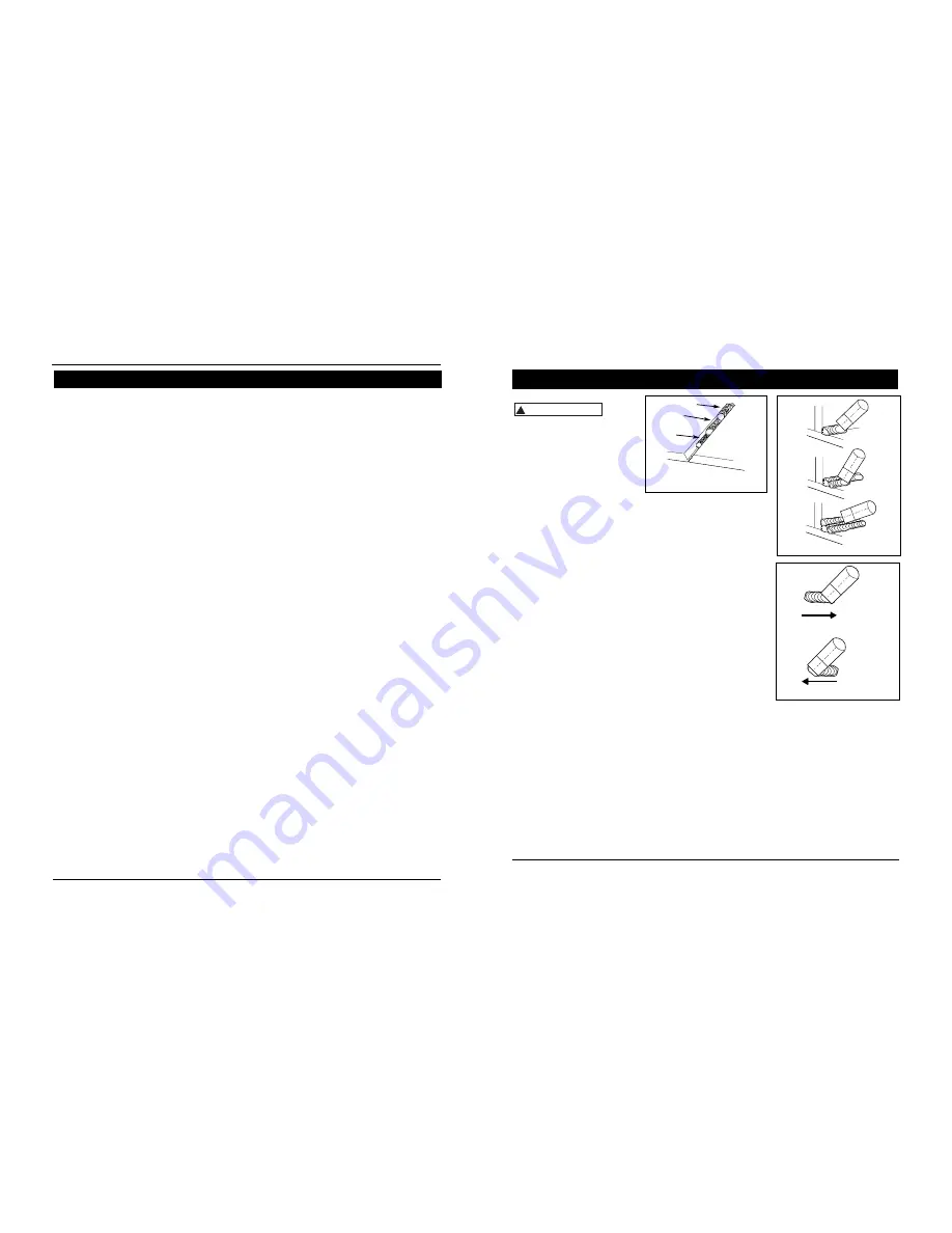
METODO USADO PARA SOLDAR
Según el tipo de material y el grosor de
la pieza de trabajo deberá usar un
método de desplazamiento de la
pistola soldadora. Para soldar
materiales delgados (de calibre 18 ó
mayor) y cualquier pieza de aluminio,
la pistola debe ubicarse al frente del
sedimento y
dirijirlo
a lo largo de la
pieza. Para soldar piezas de acero más
gruesas, ubique la pistola directamente
sobre el sedimento para aumentar la
penetración. Este método se podría
llamar de empuje (vea la Figura 10).
Instrucciones para soldar
(Continuación)
Modelos WF2050, WF2054, WF2057 & WF2058
Figura 8 - Soldadura con filete
(Ángulo de 60˚)
Cubierta
Relleno
Raíz
Figura 9 - Pasos múltiples
Figura 10
HALE
EMPUJE
Operating Instructions and Parts Manual
AC or Alternating Current
- electric
current that reverses direction
periodically. Sixty cycle current travels in
both directions sixty times per second.
Arc Length
- the distance from the end
of the electrode to the point where the
arc makes contact with the work surface.
Base Metal
- the material to be welded.
Butt Joint
- a joint between two
members aligned approximately in the
same plane.
Crater
- a pool, or pocket, that is formed
as the arc comes in contact with the base
metal.
DC or Direct Current
- electric current
which flows only in one direction. The
polarity (+ or -) determines which
direction the current is flowing.
DC Reverse Polarity
- occurs when the
electrode holder is connected to the
positive pole of the welding machine.
Reverse Polarity directs more heat into
melting the electrode rather than the
work piece. It is used on thinner material.
DC Straight Polarity
- occurs when the
electrode holder is connected to the
negative pole of the welding machine.
With straight polarity more heat is
directed to the work piece for better
penetration on thicker material.
Electrode
- a coated metal wire having
approximately the same composition as
the material being welded.
Fillet Weld
- approximately a triangle in
cross-section, joining two surfaces at right
angles to each other in a lap, T or corner
joint.
Flux
- a coating, when heated, that
produces a shielding gas around the
welding area. This gas protects the parent
and filler metals from impurities in the air.
Flux Cored Arc Welding (FCAW)
- also
called Gasless, is a welding process used
with a wire-feed welding machine. The
weld wire is tubular with flux material
contained inside for shielding.
Gas Metal Arc Welding (GMAW)
- also
called MIG, is a welding process used
with a wire feed welding machine. The
wire is solid and an inert gas is used for
shielding.
Gas Tungsten Arc Welding (GTAW)
-
also called TIG, is a welding process used
with welding equipment with a high
frequency generator. The arc is created
between a non-consumable tungsten
electrode and the work piece. Filler metal
may or may not be used.
Lap Joint
- a joint between two
overlapping members in parallel planes.
Open Circuit Voltage (OCV)
- the
voltage between the electrode and the
work clamp of the welding machine
when no current is flowing (not
welding). The OCV determines how
quickly the arc is struck.
Overlap
- occurs when the amperage is
set too low. In this instance, the molten
metal falls from the electrode without
actually fusing into the base metal.
Porosity
- gas pockets, or cavities,
formed during weld solidification. They
weaken the weld.
Penetration
- the depth into the work
piece that has been heat effected by the
arc during the welding process. A good
weld achieves 100% penetration
meaning that the entire thickness of the
work piece has been heated and
resolidified. The heat effected area
should be easily seen on the opposite
side of the weld.
Shielded Metal Arc Welding (SMAW)
- also called Stick, is a welding process
that uses a consumable electrode to
support the arc. Shielding is achieved by
the melting of the flux coating on the
electrode.
Slag
- a layer of flux soot that protects
the weld from oxides and other
contaminants while the weld is
solidifying (cooling). Slag should be
removed after weld has cooled.
Spatter
- metal particles thrown from
the weld which cool and harden on the
work surface. Spatter can be minimized
by using a spatter resistant spray on the
work piece before welding.
Tack Weld
- weld made to hold parts in
proper alignment until final welds are
made.
Travel Angle
- the angle of the
electrode in the line of welding. It varies
from 5º to 45º depending on welding
conditions.
T Joint
- made by placing the edge of
one piece of metal on the surface of the
other piece at approximately a 90º angle.
Undercut
- a condition that results when
welding amperage is too high. The
excessive amperage leaves a groove in
the base metal along both sides of the
bead which reduces the strength of the
weld.
Weld Pool or Puddle
- a volume of
molten metal in a weld prior to its
solidification as weld metal.
Weld Bead
- a narrow layer or layers of
metal deposited on the base metal as the
electrode melts. Weld bead width is
typically twice the diameter of the
electrode.
Work Angle
- the angle of the electrode
from horizontal, measured at right
angles to the line of welding.
Glossary of Welding Terms
8
www.chpower.com


