26 - 120
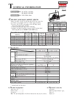
3 - SPECIFICATIONS
3.5
Tool parts
POS. DESCRIPTION
FUNCTION
PICTURE
1
Plate
Shows the product identification details
B
2
Extension pole fixing system
Fixes the extension pole
D
3
Telescopic extension pole
Allows to cut high branches w/o using a ladder
D
4
Extension pole connection
Connects the pole to the chainsaw
D
5
Fixed extension pole
Allows to cut high branches w/o using a ladder
D
6
Fixing screws
Fix the support handle
A
7
Support handle
Allows the operator to hold the tool while working
A
8
Hand guard
Protects the operator’s hand against dangerous kickback effects
A
9
Fixing screws
Fix the hand guard
A
10 Bar
Drives the cutting chain
A
11 Chain
Cuts branches, trunks, etc.
A
12
Fixing screws
Fix the front protection
A
13 Front protection
Protects the chain rotation system
A
14 Fixing nuts
Fix the bar
A-E
15 Coupling
Connects the tool to the air hose
C
16 Pneumatic valve
Drives the tool operation
C
17
Handle
Is hold to control the tool operation
C
18
ON/OFF switch
Makes the tool operate, when it is in ON position, or stops it, when in OFF position
C
19
Hand guard
Protects the hands
C
20 Safety catch
Controls the operating lever
C
21 Operating lever
Operates the tool when it is pressed
C
22 Warning plate
Indicates the safety symbols for the operator
B
23 Tap
Closes the oil reservoir
B
24 Motor
Operates the cutting bar
B
25 Connection
Connects the operating handle to the motor
B
26 Oil reservoir
Contains the lubricating oil
B
27 Ring nut
Fixes the operating handle
B
28 Brake
Stops the inertial movement of the chain
E
29
Screw
Fixes the chain brake spring
E
30 Chain direction
Is shown in the picture
E
31 Pin
Is the connection point to fix the brake spring
E
32 Chain guard
Protects the chain when the tool is not being used
F
33
Adjusting screw
Regulates the chain tension
F
34
Chain locking pin
Locks the chain in case of breakage
F
35
Screw
Locks the chain holding pin
F
-
Protective clothing
The picture shows the clothing the operator has to wear
H
-
Max. cutting diameter
The picture shows the max. diameter which can be cut according to the bar length
N
3.6 Technical details
•
8“ chainsaw weight:
............................................................................... 2.350 kg
•
10“ chainsaw weight:
............................................................................. 2.450 kg
•
Cutting bar (10) length:
.............................................................................
8” - 10”
•
Air consumption:
....................................................................................
NI/1’ 400
•
Working pressure:
...................................................................
1000 kPa (10 bar)
•
Max. cutting size with 8” bar:
.............................................................. Ø 150 mm
•
Max. cutting size with 10” bar:
............................................................ Ø 200 mm
•
Inertial chain brake (28):
...............................................................................YES
•
ON-OFF switch (18):
.....................................................................................YES
•
Active safety device (20):
..............................................................................YES
•
Adjustable lubrication of the chain bar:
.........................................................YES
•
Connection to an extension pole:
.................................................................YES
Summary of Contents for P8
Page 89: ...87 120 CAMPAGNOLA S r l CAMPAGNOLA S r l CAMPAGNOLA S r l...
Page 91: ...89 120 1 1 1 1 2 M CAMPAGNOLA S r l 1 3 E 2006 42 CE 1 4...
Page 93: ...91 120 2 2003 10 CE 2002 44 CE 81 2008 2 1 2 H H I L...
Page 95: ...93 120 3 3 1 1 3 2 11 10 8 10 17 24 18 ON OFF 20 21 28 T 11 10 3 5 3 3 3 4...
Page 97: ...95 120 3 3 7 ON OFF 18 20 21 28 11 10 19 21 32 10 3 8 22 4 4 1 H 10 11 26 SAE 30 11...
Page 99: ...97 120 5 5 4 34 5 5 5 6 1 S 2 T 5 7 M 5 8 27 17 7 6 8 9 25 24 5 9...
Page 100: ...98 120 5 5 10 ON OFF 18 OFF 28 11 10 bar ON 8 11 33 10 26 23 10 bar 16 16 17 6 6 1...
Page 103: ...101 120 6 4 mm 35 35 10 1 5 10 1 5 30 85 60 0 64 mm 0 025...
Page 104: ...102 120 6 6 3 X X X X X X X X X X X X X X X X X X X X X X X X X...
Page 105: ...103 120 7 7 1 7 2 13 25 2005 151 2002 95 2002 96 2003 108 22 1997 50 22 1997...