Operation and maintenance instructions
Series PRE proportional pressure regulator
IO-Link version
5000030186
Ver. 03
18
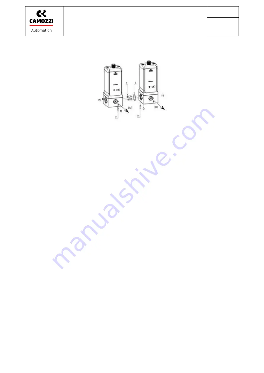
4. Tighten the four grub screws (2) until they are locked (Tightening torque: 2,5 ± 0,5 Nm)
•
There are 2 additional pneumatic ports on the PRE series electronic regulator:
o
M5 to discharge the exhaust valve to the outside. It is important to keep this port
free and clean to ensure that air is discharged without obstructions that could limit
the flow. If necessary, remove the pre-assembled filter, connect a suitable coupling
and use a hose to convey discharged air to a suitable area.
o
M5 for external servo-pilot supply. The regulator is supplied with a preassembled cap
for the versions with internal servo-pilot supply and with the fitting 6625 3-M5 for
the versions with external servo-pilot supply.
•
In order to connect the regulator with MD series, use the PRE-1/4-C kit for regulator with
G1/4 pneumatic port or use the PRE-3/8-C kit for regulator with G3/8 pneumatic port.
•
The board implements a protection against inversion of polarity on the power supply
voltage.
•
The board is also fitted with a resettable 1A fuse to limit the maximum current absorption
of the servovalve. Use a power supply unit able to deliver a current of at least 0,5A
(recommended 1.0A).
•
If UL/CSA standard compliance is required, the unit shall be supplied by an isolated power
source which fulfils at least one of the following the requirements of:
- Limited-Energy Circuit in accordance with UL/CSA 61010-1/ UL/CSA 61010-2-201
- Limited Power Source (LPS) in accordance with UL/CSA 60950-1
- a Class 2 supply source which complies with the National Electrical Code (NEC), NFPA 70,
Clause 725.121 and Canadian Electrical Code (CEC), Part I, C22.1. (typical examples are a
Class 2 transformer or a Class 2 power sources in compliance with, UL 5085-3/ CSA-C22.2
No. 66.3 or UL 1310/CSA-C22.2 No. 223). In order to respect the UL/CSA 61010
requirements, install the regulator inside a box, not in external environment.
•
The power supply voltage must be within the range of 24V±10%.
•
The board implements a protection against overload of the reference signal.
•
The M12 4 pin male connector has the following pinout. The port is configured as port A:


