A-7
Model 199 Differential Pressure Unit (DPU)
Section 2
Range Springs
The range of the dual-bellows type DPU is determined by the force required
to move the bellows through their normal range of travel.
The range springs, which are available in various ranges (see
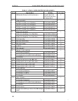
Table 1.1, page
A-4
), act with the bellows and torque tube to balance the differential pressure ap-
plied to the unit. The number of springs used and their spring rate depends on
the individual differential pressure range requirement.
Torque Tube Assembly
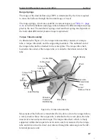
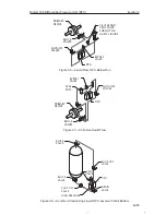
As illustrated in Figure 2.3, the torque tube assembly consists of a torque
tube, a torque tube shaft, and the supporting members. The outboard end of
the torque tube shaft is attached to the center plate. The torque tube shaft,
located in the center of the torque tube, is welded to the inboard end of the
tube.
Needle Beaing
Center Plate
Weld
Drive Arm
Valve Stem
Disc
0.200"
Bellows Travel
Valve Stem
Minature
Precision
Ball Bearing
Jewel Bearing
Torque Tube
Shaft
Torque Tube
Torque Tube
Lock Nut
O-Ring Seal
Weld
8°
Rotation
Figure 2.3—Torque tube assembly
Movement of the bellows is transmitted by the drive arm to the torque tube as
a rotary motion. Since the torque tube is attached to the center plate, the tube
must twist when subjected to torque. The torque tube shaft, which is freely
supported within the torque tube at its outer end, but connected to the torque
tube and drive arm at its inner end, rotates through the same angle as the dif-
ferential pressure unit.

