25
Model 289A Differential Pressure Indicating Switch
Section 3
Parts Replacement
Due to the new snap-acting microswitch being used in Model 289A differen-
tial pressure indicating switch, the Drive Arm and Switch & Plate Assemblies
have been redesigned. These assemblies are not backwards compatible and
have to be installed at the same time for proper operation of the Model 289A.
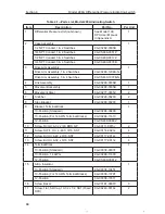
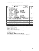
Drive Arm and Switch & Plate Assemblies
1. Remove the bezel/cover per Bezel/Lens (or Cover) Installation and Re-
moval, page 15.
2. Remove pointer (see Pointer Installation and Removal, page 17)
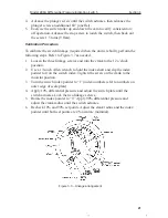
3. Remove scale plate by removing (4) Mounting Screws (see Figure 4.1).
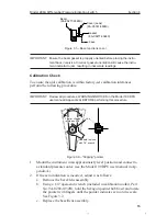
4. Disconnect the Link from the original Drive Arm Assembly (see Figure
3.4).*
5. Loosen the Clamp Screw using 1/8” Open-end Wrench (for old style
Drive Arm) or 3/32” Hex Allen Wrench (for new style Drive Arm).*
6. Carefully move the Actuator Arms away from the Cam and slide the
Drive Arm Assembly off the Torque Tube.*
7. Disconnect the switch leads from the Terminal Block.
8. Carefully remove the Grip Ring and Washer securing the Drive/Link
Plate assembly from the Switch and Plate Assembly and save for the
installation process.
9. Remove the Lock Screw securing the high side Switch and Plate Assem-
bly first and uninstall the Switch and Plate Assembly. Repeat for the low
side assembly.
10. Install and secure the replacement Switch and Plate Assemblies in the
reverse order above.
11. Install the replacement Drive Arm Assembly and ensure that the cam is
relatively centered under the cam rollers. Tighten the Clamp Screw using
3/32” Hex Allen Wrench.*
12. Reconnect the switch leads to the Terminal Block.
13. Calibrate the switches per Calibration Procedure, page 21.
*Note: These steps may be omitted if the Model 289A is already
equipped with the new Drive Arm and Switch & Plate Assemblies.


