A-26
Section 4
Model 199 Differential Pressure Unit (DPU)
WARNING: Do not reuse housing bolts. Reuse of housing bolts, especial-
ly in critical applications like hydrogen sulfide and salt water exposures,
can result in severe injury, death or substantial property damage due to
bolt failure.
7. Attach the indicator bracket to the replacement assembly, using the indi-
cator bracket screws.
8. Attach the mounting bracket using the screws provided.
9. Support the DPU and tighten and torque the pressure housing bolts in
accordance with
Table 4.2, page A-19
.
10. Attach the case assembly using case retaining screws.
11. Attach the drive arm and linkage.
12. Tighten the drive arm to the torque tube, as described below.
13. Replace any instrument components that were removed (refer to the "Im-
portant: Component Removal" notice on page A-19).
14. Calibrate the instrument before returning it to service.
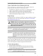
Attaching Drive Arm to Torque Tube
1/8” WRENCH
(PN 9A-0163-0044C)
CLAMP SCREW
DRIVE ARM
LINK
SINTERED
CLAMP BLOCK
TO TIGHTEN
.03 (approx)
SHAFT
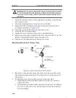
Figure 4.4—Drive arm to torque tube connection
1. Slip the drive arm over the torque tube shaft; clear the end of the torque
tube housing by approximately 0.030 inches before securing to prevent
interference.
2. To tighten the drive arm assembly onto the torque tube shaft:
a. Supporting the block and shaft, tighten the clamp screw until it is
snug to the shaft.
b. Still supporting the block/shaft, tighten the clamp screw an addition-
al 1/3 to 1/2 turn. (The screw can normally turn one full revolution
before breaking.)

