24
Section 3
Model 289A Differential Pressure Indicating Switch
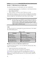
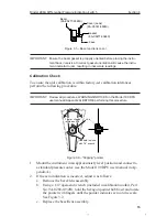
IMPORTANT: The switch index has 10 divisions, marked 0, 5, and 10. These match the
markings on the outer edge of the scale.
Example: Scale has range of 0-60 psid. Set point is 24 psid, with decreasing
pressure, (24/60 x 10 = 4).
1. Move the index pointer (item C) for the low switch from division 0 to
division 4.
2. Tighten switch lock (Item B) snug plus 1/4 turn to place the set point
within ±2% of full scale. Do not overtighten.
3. Repeat step 1 for the high switch, moving the index pointer from division
10 to division 4, and tighten the switch lock as described in step 2.
Changing Set Point of an Out-of-Service Instrument
Use the following procedure to set a set point for an instrument that is out of
service—typically, an instrument that is disconnected from process lines or
mounted on a bench.
1. Drain and vent housings.
2. Attach the calibration pressure source (air or N
2
) to the DPU HP housing.
3. Apply varying pressures and observe pointer readings for accuracy. Use a
pressure standard (Heise gage or equiv.) for reference. Change pressures
slowly in discrete steps. A “bleed-pressure” method may cause errors.
4. Change switch set point as described in
In-Service Instruments, page 23
.
5. Check the set point by changing measured pressure to actuate the switch.
For example: To verify a low-switch set point of 24 psid, apply approxi-
mately 30 psi. Reduce pressure to approximately 25 psid, hold for a few
seconds, then continue in 1/4 psid steps until the switch actuates. If the
set point is incorrect, continue instructions in
In-Service Instruments,
page 23
.
6. To measure the switch deadband, reduce the pressure to zero, then in-
crease pressure until the switch resets.
7. To verify repeatability of a set point, repeat step 5 several times. For
improved accuracy, use smaller increments of pressure. Allow extra time
for slow response gages and for test systems that have long runs of small-
bore tubing.
High alarm switches (right side of the scale) are adjusted in a similar manner.
Apply increasing pressure to establish the switch set point, and apply decreas-
ing pressure to measure the deadband.
Range Changes
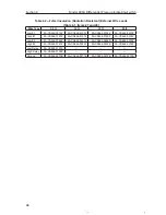
Changing the range of a Model 289A differential pressure indicating switch
typically requires replacment of the 199 DPU.


