background image

A-31

Model 199 Differential Pressure Unit 

Section 5

Table 5.1—Model 199 Parts List

Item

Description

Part No.

Per 

Unit

1

BUA (BELLOWS UNIT ASSEMBLY)

SELECT

1

2

HOUSING, PRESSURE, TAPPED (MATCH PORTS WITH 

ITEM 3)

1

HOUSING, 1 K SST, 1/4 X 1/4 NPT

9A-CS787-0071C

HOUSING, 1 K SST, 1/4 X 1/2 NPT (TOP/BOTTOM)

9A-CS787-0061C

HOUSING, 1 K SST, 1/2 X 1/4 NPT (TOP/BOTTOM)

9A-C0199-1038C

HOUSING, 1 K SST, 1/2 X 1/2 NPT

9A-CS787-0025Z

HOUSING, 3 K SST, 1/4 X 1/4 NPT

9A-CS787-0066C

HOUSING, 3 K SST, 1/4 X 1/2 NPT (TOP/BOTTOM)

9A-CS787-0057Z

HOUSING, 3 K SST, 1/2 X 1/4 NPT (TOP/BOTTOM)

9A-C0199-1042C

HOUSING, 3 K SST, 1/2 X 1/2 NPT

9A-CS787-0058C

3

HOUSING, PRESSURE, DRILLED (MATCH PORTS 

WITH ITEM 2)

1

HOUSING, 1 K SST, 1/4 X 1/4 NPT

9A-CS787-0072C

HOUSING, 1 K SST, 1/4 X 1/2 NPT (TOP/BOTTOM)

9A-CS787-0060C

HOUSING, 1 K SST, 1/2 X 1/4 NPT (TOP/BOTTOM)

9A-C0199-1037C

HOUSING, 1 K SST, 1/2 X 1/2 NPT

9A-CS787-0026Z

HOUSING, 3 K SST, 1/4 X 1/4 NPT

9A-CS787-0067C

HOUSING, 3 K SST, 1/4 X 1/2 NPT (TOP/BOTTOM)

9A-CS787-0056Z

HOUSING, 3 K SST, 1/2 X 1/4 NPT (TOP/BOTTOM)

9A-C0199-1041C

HOUSING, 3 K SST, 1/2 X 1/2 NPT

9A-CS787-0059C

4

BOLT, HOUSING, 1 K

9A-C0199-1345C

12

BOLT, HOUSING, 3 K

9A-C0220-1116J

5

PLUG, PIPE, 1/4"NPT, 316 SST

9A-C0199-0214C

2

PLUG, PIPE, 1/2"NPT, 316 SST

9A-C0199-0215C

6

GASKET, PRESSURE HOUSING, NICKEL

9A-C0199-0184C

2

7

LABEL, HIGH PRESSURE

9A-0199-0194C

1

8

LABEL, LOW PRESSURE

9A-0199-0195C

1

9

BRACKET, MOUNTING, 1 K MODEL 200A/289A

9A-C0199-1493B

1

BRACKET, MOUNTING, 3 K MODEL 200A/289A

9A-CS787-0047Z

BRACKET, MOUNTING, 3 K MODEL 581A

9A-C0199-1109B

10

BRACKET, INDICATOR - MODEL 200A/289A

9A-CS748-0006Z

1

BRACKET, INDICATOR - MODEL 581A

9A-C0197-1019C

11

SPACER, INDICATOR BRACKET - MODEL 200A/289A

9A-C0199-0006C

2

12

SCREW, HEX WASHER HEAD, 3/8-16 X 1-1/8

9A-C0002-1009T

2

13

SCREW, HEX HD, 3/8-16 X 3/4 - MODEL 581A

9A-C0116-0007J

2

14

BRACKET SPACER

9A-C0199-0003C

1

Summary of Contents for BARTON 289A

Page 1: ... 2 Installation 7 General 7 Mounting Piping DPU Installation 7 Electrical Connection Switches Relays 7 Switch Use 7 Startup 8 Switch and Relay Wiring Diagrams 9 Section 3 Maintenance and Calibration 14 Tools 14 Bezel Lens or Cover Installation and Removal 14 Calibration Check 15 Pointer Installation and Removal 16 Pointer Installation 16 Pointer Removal 16 Indicator Calibration 17 Drive Arm Tightn...

Page 2: ...al injury or incorrect function of the instrument or connected equipment IMPORTANT Indicates actions or procedures which may affect instrument operation or may lead to an instrument response that is not planned Changing Switch Set Point 22 Definitions of Terms 22 Best Practices for Set Points 22 Changing Set Point of an In Service Instrument Not Recommended for Nuclear Qualified Units 23 Changing ...

Page 3: ...ator and switch mecha nism The large cover lens allows maximum readability of the indicating pointer Switches and all adjustments are readily accessible when the cover is re moved The built in switches energize either single or dual alarm circuits when the measured differential pressures exceed predetermined limits These limits may be either maximum minimum or both Main Components Low Alarm Relay ...

Page 4: ... the switches actuate are adjustable with high and low alarm switch adjustments on the scale plate RED YELLOW BLUE BLACK 100 0 50 Mid point DP ORANGE VIOLET SWITCH CLOSED CONTACTS OPEN CONTACTS YELLOW BLUE RED YELLOW VIOLET ORANGE VIOLET BLACK A LEFT B RIGHT 100 0 50 Zero DP SWITCH CLOSED CONTACTS OPEN CONTACTS YELLOW BLUE RED YELLOW VIOLET ORANGE VIOLET BLACK A LEFT B RIGHT 100 0 50 Maximum DP SW...

Page 5: ...y low switches set for decreasing pressures switches 2 and 4 are usually high switches set for increasing pressures Relays Relays are actuated by internal switches and are available in several varia tions one or two SPDT switches one or two DPDT switches Wiring No 22 AWG is used for internal wiring and No 18 AWG is used for external wiring Differential Pressure Unit DPU For detailed information on...

Page 6: ...span 350 inches wc to 115 psig 1 or 2 DPDT Switches S401 Add 1 2 to standard accuracy Near switch setpoint 10 full scale Add 1 2 to standard accuracy For suppressed ranges Add 1 4 to standard accuracy 3 or 4 SPDT Switches Add 3 4 to standard accuracy Switch Deadband SPDT 5 of full scale DP max DPDT 6 of full scale DP max Accuracy of Repeatability 0 25 of full scale DP Nuclear Qualifications The fo...

Page 7: ...ion Switches Relays Units are supplied with either single or dual alarm switches and or relays depending on customer order The direct set switch contacts are adjustable over 5 to 95 of the scale range for SPDT switches and 6 to 94 of the scale range for DPDT switches Table 2 1 page 8 shows switch and relay wiring color coding for legacy and current configurations Figures 2 1 through 2 6 show switc...

Page 8: ...ow 2 White Red White Yellow White Blue White Red White Yellow White Blue High 1 Black Green White Black Violet Orange High 2 White Black White Green White Violet White Black White Violet White Orange SWITCHES FOR RELAYS Low Red Yellow Blue Note 1 White Brown Brown White Note 1 High Black Green White Note 1 White Gray Gray White Note 1 RELAYS Low 1 Gray Blue Brown Red Yellow Blue Low 2 White Gray W...

Page 9: ...ointer scale position NO Normally Open in shelf condition NC Normally Closed in shelf condition C Common HIGH SPDT SWITCH NO C NC CASE GROUND GREEN ORANGE VIOLET BLACK ORANGE VIOLET BLACK 8 9 10 LOW SPDT SWITCH NO 1 2 3 C NC RED YELLOW BLUE RED CASE GROUND GREEN YELLOW BLUE LOW HIGH SPDT SWITCHES NO NO C C NC NC RED YELLOW BLUE RED CASE GROUND GREEN YELLOW BLUE ORANGE VIOLET BLACK ORANGE VIOLET BL...

Page 10: ...GREEN YELLOW BLUE WHITE RED WHITE YELLOW WHITE BLUE WHITE RED WHITE YELLOW WHITE BLUE 1 2 3 4 5 6 LOW HIGH DPDT SWITCHES NO C NC NO C NC RED YELLOW BLUE RED CASE GROUND GREEN YELLOW BLUE WHITE RED WHITE YELLOW WHITE BLUE WHITE RED WHITE YELLOW WHITE BLUE 1 2 3 4 5 6 NO C NC NO C NC ORANGE VIOLET BLACK ORANGE VIOLET BLACK WHITE ORANGE WHITE VIOLET WHITE BLACK WHITE ORANGE WHITE VIOLET WHITE BLACK 7...

Page 11: ...LOW WHITE BLUE 1 2 3 4 5 6 7 NO C NC CASE GROUND GREEN ORANGE VIOLET BLACK ORANGE VIOLET BLACK 8 9 10 Figure 2 3 3 switch diagram current configuration color codes see Table 2 1 page 8 4 SWITCHES INDEPENDENTLY ADJUSTABLE NO C NC NO C NC RED YELLOW BLUE RED YELLOW BLUE WHITE RED WHITE YELLOW WHITE BLUE WHITE RED WHITE YELLOW WHITE BLUE 1 2 3 4 5 6 NO C NC NO C NC ORANGE VIOLET BLACK ORANGE CASE GRO...

Page 12: ... WHITE BROWN WHITE BROWN BROWN WHITE BROWN BROWN WHITE RED CASE GROUND GREEN YELLOW BLUE LOW HIGH SWITCHES WITH SPDT RELAYS NO NO 1 2 3 4 5 6 7 8 9 10 C C NC NC RED YELLOW WIRE NUT TYPICAL BLUE WHITE BROWN WHITE BROWN WHITE BROWN BROWN WHITE BROWN BROWN WHITE RED CASE GROUND GREEN YELLOW BLUE NO NO C C NC NC BLACK VIOLET ORANGE WHITE GRAY WHITE GRAY WHITE GRAY WHITE GRAY VIOLET BLACK GRAY WHITE GR...

Page 13: ...ROWN WHITE BROWN WHITE BROWN BROWN BROWN WHITE RED CASE GROUND GREEN YELLOW BLUE NO C NC NO 1 2 3 4 5 C NC NO C NC RED YELLOW BLUE WHITE RED WHITE YELLOW WHITE BLUE WHITE BROWN WHITE BROWN WHITE BROWN WHITE BROWN BROWN BROWN WHITE RED CASE GROUND GREEN YELLOW BLUE NO C NC LOW HIGH SWITCHES WITH DPDT RELAYS NO 6 7 8 9 10 C NC NO C NC BLACK VIOLET ORANGE WHITE BLACK WHITE VIOLET WHITE ORANGE WHITE G...

Page 14: ...aintenance repair on the in strument or DPU without first reviewing all procedures and warning caution notices in the DPU manual Tools The following tools are recommended for general maintenance of the Model 289A DP indicating switch Table 3 1 Tools Equipment Purpose Pointer Puller Pointer removal Small Screwdriver Calibration adjustment Medium Screwdriver Bezel removal and replacement 1 4 and 1 8...

Page 15: ...RTANT Review all procedures WARNINGS NOTICES in the Model 199 DPU user manual Appendix A BEFORE performing this procedure HUB Pointer slipped rotated on hub Hub held in place with 1 4 wrench Figure 3 2 Slipping pointer 1 Mount the instrument in an approximately level position and connect to a standard pressure source see the Model 199 DPU user manual in Ap pendix A 2 If the zero indication is inco...

Page 16: ...r set at zero scale Obtain 75 to 90 pointer hub engagement on the movement pinion shaft The pinion shaft must not extend through the pointer hub It may be necessary to enlarge the hub hole using a tapered broach in cluded in the calibration toolkit Part No 9A 0288 1032B 2 Lightly tap the pointer hub with a hand set or other flat end tool Use perpendicular blows to avoid bending the shaft 3 Check t...

Page 17: ... 3 3 Pointer puller Part No 9A 0163 0005B Indicator Calibration A complete calibration of instrument is required whenever the DPU assembly is replaced IMPORTANT Review all procedures WARNINGS NOTICES in the Model 199 DPU user manual Appendix A BEFORE performing this procedure 1 Securely mount the instrument in an approximately level position and connect the DPU see the Model 199 DPU user manual in...

Page 18: ...ance of about 10 times the linearity error b Check to see that the drive arm clears the end of torque tube housing by approximately 0 030 in before retightening the drive arm screw to prevent interference c While supporting the block shaft tighten clamp screw until snug to shaft d Still supporting block shaft tighten clamp screw an additional 1 3 to 1 2 turn This screw can normally turn one full r...

Page 19: ... 14 Drive Arm Tightness Test This procedure tests the tightness of the drive arm s connection to the torque tube by applying torque developed by the DPU onto a fixed drive arm Care should be taken to apply pressure slowly as torque is being applied to the connection through the torque tube drive shaft 1 With the pointer at normal 0 torque tube rotation position 0 on a normal 0 to 100 scale unit ad...

Page 20: ...ation check procedure page 15 If the instrument is out of calibration before performing a complete calibration procedure remove the bezel lens and scale plate and inspect the switch mechanism Figure 3 6 to verify the following The roller rotates without wobble or binding The cam is relatively centered under the roller The actuator arm moves freely on its pivot All switch mounting screws are tight ...

Page 21: ...hree linkage screws and turn the crank to the 12 o clock position 2 Use a 1 8 inch Allen wrench to hold the index shaft and slip the index pointer to 0 on the switch index Tighten the screw on the crank to the mid slot position 3 Turn the switch index pointer to 1 index numbers refer to numbers on outer edge of scale plate 4 Apply 10 differential pressure and adjust the switch plate until the swit...

Page 22: ...nt switch operation 9 Check the switch deadband actuate to reset by applying differential pressure first in a decreasing direction then in an increasing direction opposite for high switch direction Observe pressures To reduce dead band advance the plunger screw two flats maximum 10 Adjust the high switch to actuate at the desired pressure The procedure is the same as for the low switch Changing Sw...

Page 23: ...uclear Qualified Units Use the following procedure to set a set point for an instrument that is in ser vice when calibration pressures cannot be applied See Figure 3 8 for specific locations denoted by items A B C and D 1 Remove the bezel cover Do not remove the pointer or scale 2 Insert hex wrench in the switch adjust post 3 Loosen the switch lock screw item B 1 2 to 1 turn 4 With a hex wrench mo...

Page 24: ...andard Heise gage or equiv for reference Change pressures slowly in discrete steps A bleed pressure method may cause errors 4 Change switch set point as described in In Service Instruments page 23 5 Check the set point by changing measured pressure to actuate the switch For example To verify a low switch set point of 24 psid apply approxi mately 30 psi Reduce pressure to approximately 25 psid hold...

Page 25: ...rench for new style Drive Arm 6 Carefully move the Actuator Arms away from the Cam and slide the Drive Arm Assembly off the Torque Tube 7 Disconnect the switch leads from the Terminal Block 8 Carefully remove the Grip Ring and Washer securing the Drive Link Plate assembly from the Switch and Plate Assembly and save for the installation process 9 Remove the Lock Screw securing the high side Switch ...

Page 26: ...Primary Element to DPU Piping Refer to DPU Manual Pressure tap holes plugged and or piping plugged Clean out piping Bypass valve open or leaking Close bypass valve s and or repair leaks Liquids or gases trapped in piping Vent piping Block or shutoff valves closed Open block or shutoff valves Piping leaks on HP side Repair leaks Bellows Unit Refer to DPU Manual Housing filled with solids restrictin...

Page 27: ...lace Out of calibration Calibrate Erratic Indication Primary Element Flow pulsating Install dampening device upstream of DPU run Primary Element to DPU piping Liquid gas service or gas bubble liquid service trapped in piping Remove Vapor generator incorrectly installed Re pipe Reference leg gassy or liquid vapor izing See piping instructions in DPU Manual Bellows Unit Refer to DPU Manual Obstructe...

Page 28: ... amperes DC inductive loads cause arcing and burning of contacts Consider arc sup pression devices or relays Accumulation of fluids in piping gener ate artificial signal Vent gas or drain liquids from signal lines Calibration Techniques Failure to check set point after locking Verify set point repeatability after locking switch plate Rapid pressure change or venting system During calibration make ...

Page 29: ...29 Section 4 Model 289A Differential Pressure Indicating Switch Section 4 Assembly Drawing and Parts Lists Figure 4 1 Model 289A ...

Page 30: ...9A C0288 0035B 1 6 Movement Riser 9A C0277 0035C 2 7 Snubber 9A C0226 0028C 2 8 Stop Bracket 9A C0288 0028C 1 9 Bracket Terminal Block 1 10 Position Standard 9A C0288 0029C 10 Position For 14 AWG Terminal Blocks 9A C0288 1161C 12 Position 9A CS469 0060Z 10 Screw Rd Hd 6 32 x 3 8 BRS NP 9A C0111 0015J 2 11 Screw Sl Fil Hd 4 40 X 3 16 SST 9A C0114 0023J 4 12 Screw Bd Hd 4 40 x 3 16 SST 9A C0117 0012...

Page 31: ...CS666 1200B N Low DPDT 9A CS401 0184B N Low Relay 9A CS666 0284B N Low 1 Independently Adjustable 9A CS666 0286B N Low 2 Independently Adjustable not shown 9A CS666 0287B N Note If 3 or 4 independently adjustable switches are used Low 1 is installed in the upper left position and Low 2 is installed in the lower right position 27 External Wire Assembly Low See Table 4 2 page 34 A R 28 External Wire...

Page 32: ...0288 0016C A R 39 Strap 9A C0288 0017C A R 40 Screw 3 48 x 3 16 SST Binding Hd 3 per switch 9A C0117 0007J A R 41 Screw 8 32 x 1 4 SST Binding Hd 1 per switch 9A C0117 0016J 1 42 Retaining Ring 1 per switch 9A C0087 0015T A R 43 Washer Flat 3 SST 5 per switch 9A C0003 0045K A R 44 Bezel Assembly Bezel Lens Cover and Gasket 9A C0277 0018B 1 Bezel part of 9A C0277 0018B 9A C0277 0029C Lens Cover par...

Page 33: ... 3 independently adjustable switches when 3 position is not used not shown 9A C0258 0007C 1 Screw Switch Lock Hole Filler if switch is not installed 1 per switch not shown 9A C0111 0028J A R Screw Strap Hole Filler if switch is not installed 1 per switch not shown 9A C0119 0042J A R Calibration Kit not shown 9A 0288 1032B A R Recommended spare part If the scale plate is not identified with an SCR ...

Page 34: ...20 ft Low 1 9A CS666 0213Z 9A CS666 0190Z 9A CS666 0194Z 9A CS666 0201Z High 1 9A CS666 0140Z 9A CS666 0191Z 9A CS666 0195Z 9A CS666 0202Z Low 2 9A CS666 0166Z 9A CS666 0241Z 9A CS666 0268B 9A CS666 0203Z High 2 9A CS666 0167Z 9A CS666 0242Z 9A CS666 0269B 9A CS666 0204Z Low Relay 9A CS594 0137Z High Relay 9A CS594 0138Z Ground 9A CS666 0270B 9A CS666 0271B 9A CS666 0272B 9A CS666 0273B ...

Page 35: ... PRESSURE RATING PSI MPa HOUSING MATERIAL PRESSURE CONNECTION DIM A INCHES mm DIM B INCHES mm DIM C INCHES mm DIM D INCHES mm BOLTS TOP BOTTOM 1 000 6 9 FORGED STNL ST 316 1 2 NPT 1 4 NPT 1 4 NPT 1 2 NPT 1 4 NPT 1 2 NPT 1 4 NPT 1 2 NPT 9 29 32 251 6 6 5 8 168 3 2 50 8 2 9 64 51 2 12 3 000 20 7 10 5 32 257 9 7 1 8 181 0 2 50 8 2 9 64 51 2 12 NOTES Cast aluminum pipe mount supplied unless otherwise ...

Page 36: ... Model 289A side view see Table 5 1 page 35 for dimensions A C and D Figure 5 3 Model 289A rear view see Table 5 1 page 35 for dimension B IMPORTANT Model 289A version configurations are limited to nuclear applications also refer to the Model 199 DPU user manual in Appendix A ...

Page 37: ...ND EXCLUDES ALL OTHER EXPRESSED OR IMPLIED WARRANTIES OF MERCHANTABILITY OR FITNESS FOR A PARTICULAR PURPOSE OR OTHERWISE 2 Components manufactured by any supplier other than Cameron shall bear only the war ranty made by the manufacturer of that product and Cameron assumes no responsibility for the performance or reliability of the unit as a whole 3 In no event shall Cameron be liable for indirect...

Page 38: ...stallation Operation A 9 Unpacking A 9 Mounting A 9 Flush or Panel Mounting A 9 Piping Standard Practices A 9 All Applications Flow and Liquid Level A 9 Flow Applications A 10 Liquid Level Applications A 10 Piping Diagrams A 11 General Startup Practice Considerations A 17 Section 4 Maintenance Adjustment Calibration A 18 Tools Required for Maintenance and Calibration A 18 DPU Inspection and Cleani...

Page 39: ...2 3 3 4 inch Diameter Bellows with Kickoff Spring A 23 Setting Bellows Travel A 25 Bellows Unit Assembly BUA Replacement A 25 Attaching Drive Arm to Torque Tube A 26 Drive Arm Tightness Test A 27 Adjusting Pulsation Dampener A 27 Troubleshooting A 27 Section 5 Parts Drawing List A 30 Section 6 Dimensional Drawings A 35 Technical Support Cameron Measurement Systems Division 14450 John F Kennedy Blv...

Page 40: ...escription The Model 199 DPU is a dual bellows assembly enclosed within pressure housings The dual bellows assembly consists of two opposing internally con nected liquid filled bellows a center plate range springs overrange valves and a torque tube assembly The pressure housings are connected by pipe or tubing to the primary device located in the system piping Variations in differential pressure w...

Page 41: ...eel or Inconel Bellows 2 1 8 55 mm O D 3 3 4 95 mm O D 1 000 69 0 15 psi to 0 115 psi 0 1 bar to 0 7 9 bar 0 10 w c to 0 400 w c 0 25 mbar to 0 995 mbar 3 000 207 Net Volume L P Head cu in 35 cu in 575 cc 30 cu in 490 cc Net Volume H P Head cu in 31 cu in 510 cc 26 cu in 425 cc Displacement cu in for full scale travel 0 5 cu in 8 2 cc 1 5 cu in 25 cc NOTES Zero center or split ranges available on ...

Page 42: ...mping Valve Plug Figure 2 1 199 BUA cutaway Pressure Housings The two pressure housings of the Model 199 DPU are available in the various safe working pressure ratings defined in Table 1 1 page A 4 and in the dimen sional drawings in Section 6 Each pressure housing has two tapped connection ports one port is located in the top of the housing the other port is located in the bottom of the housing B...

Page 43: ...eway for the transfer of fill liquid between the two bellows This opening also allows the bellows to be connected internally by a valve stem Drive Arm Hole Plug DO NOT LOOSEN Retainer Screws Range Spring Assembly Push Rod Lock Nut Range Springs Torque Tube Shaft Torque Tube Gland Nut DO NOT LOOSEN 2 1 8 Bellows Unit Assembly BUA Spring Post Drive Arm Hole Plug DO NOT LOOSEN Range Spring Assembly R...

Page 44: ...s The outboard end of the torque tube shaft is attached to the center plate The torque tube shaft located in the center of the torque tube is welded to the inboard end of the tube Needle Beaing Center Plate Weld Drive Arm Valve Stem Disc 0 200 Bellows Travel Valve Stem Minature Precision Ball Bearing Jewel Bearing Torque Tube Shaft Torque Tube Torque Tube Lock Nut O Ring Seal Weld 8 Rotation Figur...

Page 45: ...1 page A 5 controls the flow of fill liquid between the high and low pressure bellows with an externally adjustable pul sation dampener needle valve Restriction of liquid flow reduces the effects of pulsation In applications where pulsation is not a problem the needle valve is set to the full open position ...

Page 46: ...e panel or wall Refer to the instrument s installation manual for mounting details Piping Standard Practices All Applications Flow and Liquid Level 1 Shorten the distance between the primary device and the DPU as much as possible Distances exceeding 100 feet are not recommended For dis tances up to 50 feet use 1 4 inch or 3 8 inch pipe or tubing For runs of 50 to 100 feet use 1 2 inch pipe or tubi...

Page 47: ...sing is connected to the upstream tap of the primary device IMPORTANT To prevent overheating the DPU during blowdown monitor the tempera ture by placing hands on the pipe between the DPU and the manifold pipe containing the vent valves Liquid Level Applications The process media may be used as a reference leg seal fluid if it will condense in the reference leg under all conditions If the process o...

Page 48: ...ram best suited for the application as a guide for piping configuration BLOCK VALVES PRIMARY DEVICE STATIC PRESSURE CONNECTION USE ONLY ONE BYPASS VALVES VENT VALVE SHUT OFF VALVES DPU Figure 3 1 Gas Flow DPU Above Run BLOCK VALVES PRIMARY DEVICE STATIC PRESSURE CONNECTION USE ONLY ONE BYPASS VALVES VENT VALVE SHUT OFF VALVES DPU DRIP POTS Figure 3 2 Gas Flow DPU Below Run ...

Page 49: ...SE ONLY ONE BYPASS VALVES VENT VALVE SHUT OFF VALVES DPU Figure 3 3 Gas Flow Hydrates Present DPU PLUGS BLOCK VALVES CONDENSING RESERVOIR PRIMARY DEVICE SHUT OFF VALVES VENT VALVES OPTIONAL Figure 3 4 Steam Flow DPU Below Run BLOCK VALVES PRIMARY DEVICE BYPASS VALVE SHUT OFF VALVES DPU Figure 3 5 Liquid Flow DPU Above Run ...

Page 50: ...GASSY LIQUIDS SHUT OFF VALVES DPU Figure 3 6 Liquid Flow DPU Below Run BLOCK VALVES SEAL POTS PRIMARY DEVICE BYPASS VALVE SHUT OFF VALVES DPU Figure 3 7 Corrosive Liquid Flow DRAIN VALVE BLOCK VALVE HIGH PRESSURE DPU BLOCK VALVE SHUT OFF VALVE VENT VALVE SHUT OFF VALVE Figure 3 8 Cool Non Condensing Liquid DPU Level with Tank Bottom ...

Page 51: ...OCK VALVE DRAIN VALVE DPU SHUT OFF VALVE BLOCK VALVE Figure 3 9 Cool Non Condensing Liquid DPU Below Tank HIGH PRESSURE SHUT OFF VALVE REFERENCE LEG 2 CROSS BYPASS VALVE VENT VALVE BLOCK VALVE BLOCK VALVE DPU SHUT OFF VALVE DRAIN VALVE Figure 3 10 DPU Below Tank Bottom with Reference Leg ...

Page 52: ...LENGTH 6 INCHES DPU BLOCK VALVE VAPOR GENERATOR Figure 3 11 Liquid CO2 LOW PRESSURE HIGH PRESSURE SHUT OFF VALVE INVERTED U GAS TRAP VAPOR GENERATOR FLAT TUBULAR SPIRAL IN OUTER 1 3 OF TANK INSULATION KEEP DEAD LEG BETWEEN TANK AND SPIRAL 5 INCHES OR LESS MINIMUM LENGTH 12 INCHES BLOCK VALVE BLOCK VALVE DPU Figure 3 12 Cryogenic Liquids ...

Page 53: ... VALVES HIGH PRESSURE GAS SUPPLY SIGHT FLOW GAGE BYPASS VALVE DPU INPUT GAS REGULATOR Figure 3 13 Bubbler System SHUT OFF VALVES BLOCK VALVES HIGH PRESSURE GAS SUPPLY INPUT GAS REGULATOR SIGHT FLOW GAGES WITH THROTTLING VALVES BYPASS VALVE DPU Figure 3 14 Liquid Specific Gravity ...

Page 54: ... shutoff valve This proce dure equalizes the pressure between both sides of the instrument The instrument should indicate zero b If the instrument does not indicate zero check for gas or liquid en trapment in the lines or in the DPU depending on the orientation of the piping layout and service c If necessary adjust the pen or pointer by turning the zero adjust on the instrument 3 Check the manifol...

Page 55: ...housings require periodic inspection and cleaning Always check for internal pressure using the procedure below before removing the DPU housing bolts Pressure Check procedure WARNING Failure to perform this procedure can result in severe injury death or substantial property damage due to the release of internal pressure If the DPU has been installed in gas applications with working pressures greate...

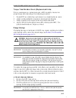
Page 56: ...als 6 Install NEW pressure housing bolts and torque in accordance with Table 4 2 WARNING Do not reuse housing bolts Reuse of housing bolts espe cially in critical applications like hydrogen sulfide and salt water expo sures can result in severe injury death or substantial property damage due to bolt failure Table 4 2 Standard Bolt Torque Ratings SWP Housing Mat l Bolt Mat l Size Qty Part No Lube N...

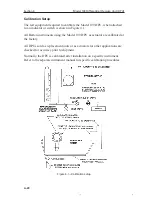
Page 57: ...e 4 1 All Barton instruments using the Model 199 DPU as actuator are calibrated at the factory All DPUs sold as replacement units or as actuators for other applications are checked for accuracy prior to shipment Normally the DPU is calibrated after installation on a specific instrument Refer to the separate instrument manual for specific calibration procedures Figure 4 1 Calibration setup ...

Page 58: ...essure PERFORM THE PRESSURE CHECK BEFORE REMOVING DPU HOUSING BOLTS IMPORTANT If accumulation of solids or semi solids is extensive remove the hous ings carefully to prevent damaging the bellows IMPORTANT The calibration range of the DPU was carefully set at the factory The following procedure maintains the original factory bellows travel setting while the range spring change is performed This pro...

Page 59: ... service 2 Remove the pressure housing bolts and the low pressure housing 3 With the pointer set at zero remove the lock nut retainer nuts and the range spring assembly To remove the range spring assembly rotate the assembly counterclockwise while pulling outward on the assembly IMPORTANT The pointer will shift from zero This is a normal action and the pointer should not be readjusted at this poin...

Page 60: ... modified 7 16 12 point box wrench for tighten ing Figure 4 3 Figure 4 3 Wrench modification 1 Remove the instrument from service Set the pointer at zero using the instrument zero adjustment 2 Remove the pressure housing bolts and remove the low pressure housing 3 With the pointer set at zero remove the lock nut spring retainer nuts washer and lock nut and range spring assembly IMPORTANT The point...

Page 61: ...heck the back clearance between the kickoff spring and the slot Use a wire feeler gage or comparable measuring device The clearance between slots will vary but must be at least 0 005 in to prevent interference with instrument zero Add or remove washers as required to obtain the proper clearance Tighten the lock nut securely 10 Install the jam nut and lock the spud to the push rod Hold with pliers ...

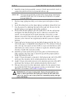
Page 62: ...ntial property damage due to the release of internal pressure perform the pressure check procedure on page A 18 before removing the DPU housing bolts IMPORTANT If accumulation of solids or semi solids is extensive remove the hous ings carefully to prevent damaging the bellows IMPORTANT Component Removal See the manual for the actuated instrument for particular components that must be removed to ga...

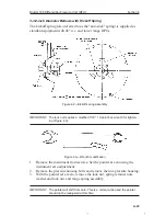
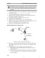
Page 63: ...o the torque tube as described below 13 Replace any instrument components that were removed refer to the Im portant Component Removal notice on page A 19 14 Calibrate the instrument before returning it to service Attaching Drive Arm to Torque Tube 1 8 WRENCH PN 9A 0163 0044C CLAMP SCREW DRIVE ARM LINK SINTERED CLAMP BLOCK TO TIGHTEN 03 approx SHAFT Figure 4 4 Drive arm to torque tube connection 1 ...

Page 64: ...nits it will be necessary to apply pressure to establish a reference point to check for zero shift 2 Pressurize the DPU to full calibrated scale DP 100 of full scale range to apply 8 degrees of torque tube equivalent torque to the connection 3 Observe the shift in the unit zero following DPU depressurization as required and drive arm stop bracket readjusting to allow free movement of drive arm and...

Page 65: ...dia Piping from Primary Element to DPU Pressure tap holes plugged Clean out piping Bypass valve open or leaking Close bypass valve s or repair leaks Liquids or gases trapped in piping Vent piping Block or shutoff valves closed Open block or shut off valves Piping leaks HP side Repair leaks Bellows Unit Housing s filled up with solids restricting bellows movement Clean out housing s Gas trapped liq...

Page 66: ...or DPU tampered with Return BUA for repair Mechanism Loose links or movements Repair or replace Out of calibration Calibrate Erratic Indication Primary Flow pulsating Install dampening device upstream of DPU run Piping from Primary Element to DPU Liquid trapped in gas piping or gas bubble in liquid piping Remove see Startup Procedure Section 3 Vapor generator incor rectly installed Repipe Referenc...

Page 67: ...Section 5 Model 199 Differential Pressure Unit Section 5 Parts Drawing List Figure 5 1 Model 199 DPU parts drawing indicator and indicator switch mounting brackets vary as shown see 200A 289A and 581A insets ...

Page 68: ... 9A C0199 1037C HOUSING 1 K SST 1 2 X 1 2 NPT 9A CS787 0026Z HOUSING 3 K SST 1 4 X 1 4 NPT 9A CS787 0067C HOUSING 3 K SST 1 4 X 1 2 NPT TOP BOTTOM 9A CS787 0056Z HOUSING 3 K SST 1 2 X 1 4 NPT TOP BOTTOM 9A C0199 1041C HOUSING 3 K SST 1 2 X 1 2 NPT 9A CS787 0059C 4 BOLT HOUSING 1 K 9A C0199 1345C 12 BOLT HOUSING 3 K 9A C0220 1116J 5 PLUG PIPE 1 4 NPT 316 SST 9A C0199 0214C 2 PLUG PIPE 1 2 NPT 316 S...

Page 69: ...0210 0012J SCREW CAP HEX HD 3 8 16 X 3 4 ST ZP 3 K MODEL 581A 9A C0116 0007J 22 SCREW CAP HEX HD 3 8 16 X 1 ST ZP MODEL 200A 289A 9A C0210 1007J 1 SCREW HEX HD 3 8 16 X 1 MODEL 581A 9A C0116 0006J 23 SPACER CENTER PLATE MODEL 200A 289A 9A CS787 0009Z 1 24 SPACER BLACK EPOXY 1 K MODEL 200A 289A 9A CS787 0006Z 2 25 SPRING PUSH ROD 9A C0199 0049C 1 26 LOCK NUT SPRING ADJUST 9A C0199 0144C 1 27 SPRING...

Page 70: ... C0199 1415B SPRING ASSY INC 156 167 WC 9A C0199 1398B SPRING ASSY INC 168 183 WC 9A C0199 1403B SPRING ASSY INC 184 195 WC 9A C0199 1407B SPRING ASSY INC 196 212 WC 9A C0199 1426B SPRING ASSY INC 213 232 WC 9A C0199 1401B SPRING ASSY INC 233 245 WC 9A C0199 1406B SPRING ASSY INC 246 258 WC 9A C0199 1417B SPRING ASSY INC 259 276 WC 9A C0199 1418B SPRING ASSY INC 277 291 WC 9A C0199 1419B SPRING AS...

Page 71: ...RING ASSY INC 0 45 PSI 9A C0199 1427B SPRING ASSY INC 0 50 PSI 9A C0199 1423B SPRING ASSY INC 0 60 PSI 9A C0199 1445B SPRING ASSY INC 0 75 PSI 9A C0199 1446B SPRING ASSY INC 0 80 PSI 9A C0199 1464B SPRING ASSY INC 0 90 PSI 9A C0199 1465B SPRING ASSY INC 0 100 PSI 9A C0199 1466B SPRING ASSY INC 0 115 PSI 9A C0199 1467B 32 SCREW SET 6 32 X 1 4 MODEL 581A 9A C0320 1010J 1 ...

Page 72: ...A 35 Model 199 Differential Pressure Unit DPU Section 6 Section 6 Dimensional Drawings Figure 6 1 Dimensional drawing Model 199 DPU rear view Figure 6 2 Dimensional drawing Model 199 DPU side view ...

Page 73: ...del 199 DPU Dimensions Pressure Rating psi bar Dim A inches mm Dim B inches mm Dim C inches mm Bolts 1 000 69 6 5 8 168 3 2 50 8 2 9 64 54 4 12 3 000 207 Ø 7 177 8 2 50 8 2 9 64 54 4 12 All Standard pipe fittings furnished by customer Metric conversions are approximate ...

Page 74: ...D EXCLUDES ALL OTHER EXPRESSED OR IMPLIED WARRANTIES OF MERCHANTABILITY OR FIT NESS FOR A PARTICULAR PURPOSE OR OTHERWISE 2 Components manufactured by any supplier other than Cameron shall bear only the warranty made by the manufacturer of that product and Cameron assumes no respon sibility for the performance or reliability of the unit as a whole 3 In no event shall Cameron be liable for indirect...

Page 75: ...R U S S I A ms kl c a m com 603 5569 0501 ...

Reviews: