After starting, check that the pump works within
its field of performance and that the absorbed
current shown on the name-plate is not exceeded;
otherwise adjust the delivery gate valve.
Avoid long operation with a closed valve.
5.3. Self-priming
(Capability to clear the air in the suction pipe
when starting
with the pump located above the
water level
and when the suction pipe cannot be
filled manually, as in the case of a missing foot
valve).
Maximum suction lifts and minimum self-priming
times (see the data sheet) are reached with a
standard electric motor (n = 2900 rpm), air-free
water with a temperature below 25 °C and a
single suction pipe with inlet diameter equal to
that of the suction connection of the pump.
Conditions for self-priming:
• Pump casing filled with water up to suction port
level before starting.
Note that with suction lift above 1,5-2 m
(without a foot valve or a check valve into
the suction pipe) the filling operation must
be repeated before each start-up.
• Suction and discharge valves completely
opened and pipes not obstructed.
• Strainer basket not obstructed.
• Suction pipe with connections perfectly airtight,
and properly immersed in the water to be lifted.
• O-ring on the strainer casing and mechanical
seal perfectly airtight (properly seated, clean
and not damaged).
• Hand wheels on strainer cover and thumbscrew
drain plug on strainer casing tightened to
prevent air entering.
• Discharge pipe without check valve, with
minimum 80 cm straight vertical free pipe above
discharge port. With suction lift below 2 m
vertical section on the pump can be 50 cm. With
suction lift lower than 1 m, an elbow can be
mounted directly onto the delivery port without a
vertical section of piping.
On expiry of the foreseen times, make sure
(through the transparent strainer cover) pump
priming has taken place and that water is flowing
regularly.
If the pump does not prime, check all
conditions above and remedy where necessary.
Repeat the priming operation again after the
pump has been completely filled with cold water.
Avoid long operation with an unprimed pump
or with a suction pipe not immersed in the
water
i.e. if water level of the pool falls too low.
By lowering the water to a level below the
skimmers and other suction ports (for emptying of
the pool), keep open only the gate valve in the
pipe for suction from the bottom (main drain).
6. Maintenance
The motors with supply current directly
switched by thermally sensitive switches can
start automatically.
Disconnect electrical power before
any servicing operation and make
sure the pump cannot be accidentally
switched on.
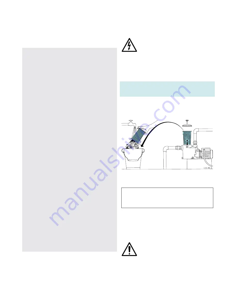
Inspect and clean the strainer basket
periodically.
The frequency of cleaning depends
on operation time of the pump, pool environment,
wind (for open air swimming pools) and the
number and behaviour of the bathers.
With the
pump located below water level
,
close the suction and delivery gate valves before
removing the cover.
The strainer can be easily accessed by removing
the strainer cover (
fig. 3
).
ATTENTION: do not use oil to lubricate the
O-ring seal. Use only water and neutral soap
to clean the transparent strainer cover. Do
not use solvents.
After cleaning, put the strainer basket in its
proper position. Fill with water up to suction port
level (see
section 5.2.
).
Position the strainer cover properly with the O-
ring seal on the casing and tighten the
handwheels uniformly.
Disinfectant or chemical products for
water treatment must not be poured
directly into the pump.
Risk of reactions and emission of
harmful fumes. Risk of corrosion in stagnant
water conditions (also with an increase in
temperature and decrease of pH value).
If the event of prolonged standstill periods or
if freezing may be expected, drain the pump
completely
by removing the two thumbscrew
drain plugs with reusable O-ring gaskets (
fig. 4
).
Fig. 3
Removing and cleaning the strainer
10