3.2. Suction pipe
The suction pipe must be perfectly airtight.
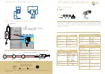
With a
pump located below water level
(inflow
under positive suction head) (
section 10.
,
fig. 7
),
install inlet and outlet valves to isolate the pump.
With a
pump located permanently above the
water level
(suction lift operation), with various
suction pipes (for skimmers, main drain, fitting for
vacuum cleaner), connect all the pipes with their
own gate valve to a manifold. As far as possible,
locate the pipes and the manifold below water level
with the pump being reached by a single vertical
pipe (see
section 11.
,
figure 8b
and
section 5.3.
).
With a pump located permanently above the water
level of a swimming pool, avoid suction lifts higher
than 3 m with respect to the main drain. With a
suction lift above 1,5 m fit a check valve
(accessible) in the suction line from the main drain.
In operating with
flexible hoses
, use a reinforced
spiral suction hose in order to avoid hose
narrowing due to suction vacuum.
4. Electrical connection
Electrical connection must be carried
out only by a qualified electrician in
accordance with local regulations.
Follow all safety standards.
The unit must be properly earthed (grounded).
Connect the earthing (grounding) conductor to
the terminal with the marking.
Compare the frequency and mains voltage with
the name-plate data and connect the supply
conductors to the terminals in accordance with the
appropriate diagram inside the terminal box cover.
ATTENTION: never allow washers or other
metal parts to fall into the internal cable
opening between the terminal box and stator.
If this occurs, dismantle the motor to recover
the object which has fallen inside.
If the terminal box is provided with and inlet
gland, use a flexible power supply cord of the
H07 RN-F type. If the terminal box is provided
with an inlet bushing, connect the power supply
cord through a conduit.
For use in swimming pools, garden ponds and
similar places, a
residual current device
with
I
Δ
N not exceeding 30 mA must be installed in the
supply circuit.
Install a
device for disconnection from the
mains
(switch) with a contact separation of at
least 3 mm on all poles.
With a three-phase motor install an overload
protection device appropriate for the rated current
of the pump.
Single-phase MPCM Compact Pool pumps
are
supplied with a capacitor connected to the
terminals and (for 220-240 V - 50 Hz) with an
incorporated thermal protector.
5.
1.
Starting
5.1. Checking the direction of rotation
ATTENTION:
when the pump is started for the
first time,
with three-phase motors check the
direction of rotation
.
With the three-phase models
MPC 5, 6, 7,
check the direction of rotation before filling the
pump (see also
section 8.
).
First check that the shaft turns by hand.
For this purpose use the screwdriver notch on the
shaft end at the motor fan side. Turn the shaft by
hand only in the direction indicated by the arrows
on the pump casing.
Do not start the motor if the shaft is jammed.
If jammed, the impeller may unscrew should
the motor start rotating backwards.
Reverse
rotation can also damage the mechanical seal.
Momentarily start the motor
to check rotation of
the pump shaft, which must be as shown by the
arrows on the pump casing: clockwise when
viewing the shaft from the motor end. Otherwise,
disconnect electrical power and reverse the
connections of two phases.
5.2. Filling
ATTENTION: avoid running dry.
When operating with the
pump below water
level
(inflow under positive suction head), fill the
pump by opening the suction gate valve slowly
and completely, keeping the delivery gate valve
open to release the air.
When the pump is located above the water
level
(suction lift operation) fill the pump with
water up to suction port level through the opening
on the strainer after removing the cover (
fig. 2
).
Fig. 2
Filling
9