23
Residual risks
In case of malfunction of the device, remove the electric supply and, if necessary, close the drain valve. To facilitate checking and maintenance
operations it is recommended to close the inlet valve of the device to allow its cooling: in this condition, check that the flow rate in the various
circulators of the system is sufficient. If it is necessary to interrupt the cycle in progress (cleaning, additive addition or sensors check) it is necessary to
reset the device: this operation cancels all the alarms and anomalies present and restores the pressures necessary for filtration. To restore the correct
operating conditions it is necessary to wait for the time necessary for the correct switching of the valves and the device filling up.
Given the presence of various potentially dangerous factors (high temperature of the water and surfaces, electrical voltage, high weight of the
device, possible collection of toxic and non-drinking liquids) all operations must be carried out by qualified technical personnel, according to current
regulations and being very careful to the operations performed and the status of the device. During the device transport and handling it is possible that
some seals and the leg support nuts may come loose. Perform a visual check and make sure that the device legs nuts are tightened with a torque of
25 Nm. Do not remove the nuts and bolts used for fastening the legs. Do not remove or loosen the bolts used for fastening the cover.
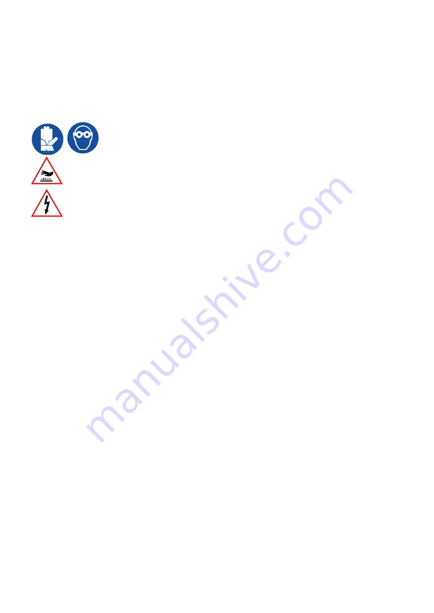
Attention during draining and/or maintenance, if the pressure is not discharged correctly, it is possible that part of the
liquid contained may splash: use a mask, gloves and protective devices to avoid contact of hot and/or aggressive liquids
with eyes, skin and various parts of the body. During handling, installation and maintenance use protective gloves.
Always check the presence and correct installation of the insulation: if there is no insulation, avoid the flow of hot water. Always check
the presence and correct installation of the gearmotor shaft protection: if this protective device is not installed, do not start the cleaning
cycles, do not add additives and do not use the motor.
Do not open the controller without having first cut-off the electrical supply through a suitable cut-off device: do not electrically supply
the device if the controller or one of its components are open and/or do not have the protections against contact with live parts.
To avoid malfunctions and damage to people or property, always use protective devices suitable to ensure compliance with the maximum pressures
and the maximum and minimum operating temperatures stated by the manufacturer in all conditions of use. The device must not be installed in
contact or near sources of heat and/or fuels: respect a minimum free distance around the device of 50 cm.
Maintenance must only be carried out by qualified technical personnel: before working on the device, all necessary measures must be taken to
ensure safety of the device and of all its parts. This safety condition must be guaranteed until the device is put back into service and must take into
consideration all possible sources of danger such as (and not exclusive): electrical dangers (electrocution, projection of incandescent material, etc.),
thermal dangers (burns), mechanical dangers (abrasions, bruises, etc...), chemical dangers related to the liquid contained and hydraulic dangers
(flooding, etc...).
17 Manufacturer's liability and warranty
With reference to the indications in this instruction manual, the company Caleffi S.p.A., declines all responsibility in case of:
• use of the strainer contrary to national laws on safety and accident prevention
• failure to comply with the instructions provided in this manual
• unauthorized strainer changes
• use by untrained or unauthorized personnel
• operations beyond the limits of use or the indications in this manual
• lack or insufficient maintenance
• use of non-original spare parts or spare parts not authorized by the manufacturer
• improper use or different from what is explicitly indicated in this manual
• installation, commissioning, maintenance not performed according to the instructions in this manual or performed by unqualified personnel or non
properly trained
• problems deriving from the system in which the device is installed or incorrect system design
• transport or storage not in accordance with local safety regulations or the instructions contained in this manual
ATTENTION
The instructions given in this manual do not replace, but summarize the obligations for compliance with the current legislation on
accident prevention safety regulations.
The warranty is valid if:
- the installation is carried out correctly, as indicated in the manual delivered
- the conditions of use suggested in the manual delivered have been respected
The warranty is voided if:
• the points described above were not respected
• the characteristics of the system do not correspond to those indicated in the manual delivered
• the product undergoes damage deriving from external causes
• the product is installed in unsuitable environments
• unauthorized tampering is made
• non-original spare parts are fitted
• the damage or the total or partial removal of the CE label automatically invalidates every form of guarantee
• the device is used for a purpose other than that expressly indicated in the manual
• the device is used with liquids or additives or substances different from those specified for use or in temperature and pressure conditions outside
the declared limits
• electrical loads of contacts and inputs are not respected
• the installation is not carried out properly and the necessary electrical and hydraulic protection devices are not installed and serviced
• the installation is carried out in an unsuitable room without the necessary elements to avoid damages in case of liquid leakage during maintenance
or for exceptional reasons, accidents, disasters and unpredictable or uncontrollable events such as earthquakes, floods, wars, etc.
The place of jurisdiction for any disputes is the court of Novara.


