15
2. Remove the cover;
3. Remove the two screws holding the control box to the
heat transfer tube assembly. Sliding the control box in the
appropriate direction will unlock it form the heat transfer
tube assembly;
4. Carefully remove any build-up from the thermal switch
surface;
CAUTION
Do not dent or scratch the surface of the thermal
switch. If the thermal switch is damaged, it must be
replaced.
5. Clear and remove any build-up or obstruction inside the
heat transfer tube;
6. Re-mount, lock and fasten the control box with the 2
screws removed in step 3;
7. Re-attach the assembly cover with the screws removed in
step 1;
8. Re-establish power to the appliance.
5.0 FURNACE INFORMATION
Model:
Serial number:
Furnace installation date:
Service telephone #-Day:
Night:
Dealer name and address:
START-UP RESULTS
Nozzle:
Pressure:
lb/po
2
Burner adjustments:
Primary air
Fine air
Drawer Assembly
CO
2
:
% Smoke
scale:
(Bacharach)
Gross stack temperature:
°F
Ambient temperature:
°F
Chimney draft :
" W.C.
Overfire draft :
" W.C.
Test performed by:
Summary of Contents for CBMAAA060120
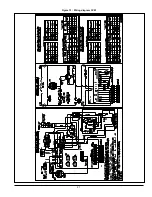
Page 21: ...21 Figure 13 Wiring diagram CVM ...
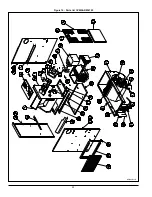
Page 22: ...22 Figure 14 Parts list CVMAAR036105 B50003 Rev D ...
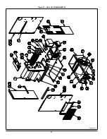
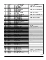
Page 24: ...24 Figure 15 Parts list CVMAAR060120 B50004 Rev F ...
Page 48: ...23 Figure 13 Diagramme électrique CVM ...
Page 49: ...24 Figure 14 Liste de pièces CVMAAR036105 B50003 Rev D ...
Page 51: ...26 Figure 15 Liste de pièces CVMAAR060120 B50004 Rev F ...


