7
This furnace is certified for use with a Type “L” vent
(maximum flue gas temperature 302°C (575°F)). The f lue
pipe clearance knockout in the front top or side panel should
be removed. Install the flue elbow so that it exits the furnace
cabinet through that opening.
Pre-installation vent system inspection
Before this furnace is installed, it is strongly recommended
that any existing vent system be completely inspected.
On any chimney or vent, this should include the following:
a. Inspection for any deterioration in the chimney or vent.
If deterioration is discovered, the chimney must be
repaired or the vent replaced;
b. Inspection to ascertain that the vent system is clear and
free of obstructions. Any blockages must be removed
before installing this furnace;
c.
Cleaning the chimney or vent if previously used for
venting a solid fuel burning appliance or fireplace;
d. Confirming that all unused chimney or vent connections
are properly sealed;
e. Verification that the chimney is properly lined and sized
per the applicable codes. (Please refer to list of codes
in Part 1.2)
Masonry Chimneys
This furnace may be vented into an existing masonry
chimney. However, it must not be vented into a chimney
servicing a solid fuel-burning appliance. Before venting this
furnace into a chimney, the chimney must be checked for
deterioration and repaired if necessary. The chimney must
be properly lined and sized per local and/or national codes.
The chimney must be of sufficient area to accommodate the
total flue products of all appliances vented into the chimney.
The following requirements are provided for a safe venting
system:
a. Ensure that the chimney flue is clear of any dirt or
debris;
b. Ensure that the chimney is not servicing an open
fireplace;
c.
Never reduce the pipe size below the outlet size of the
furnace;
d. All pipes should be supported, using the proper clamps
and/or straps. These supports should be installed at
least every 4 feet;
e. All horizontal runs of pipe should have at least 20 mm
of upward slope per 1 m (1/4” per 1');
f.
All runs of pipe should be as short as possible with as
few turns as possible;
g. Seams should be tightly joined and checked for leaks;
h. The flue pipe must not extend into the chimney but be
flush with the inside wall;
i.
The chimney must extend 0.9 m (3') above the highest
point where it passes through a roof of a building and at
least 0.6 m (2') higher than any portion of a building
within a horizontal distance of 3 m (10'). It shall also be
extended at least 1.5 m (5') above the highest
connected equipment flue collar;
j.
Check local codes for any variances.
Factory Built Chimneys
Approved factory built chimneys may be used. Refer to
chimney manufacturer’s instructions for proper installation.
2.4.4
Draft Regulator
The draft regulator supplied with the furnace must be used
for proper functioning. Installation instructions are included
with the control.
2.4.5
Blocked vent shut-off (BVSO)
For chimney venting
All oil furnaces installed in Canada must have a blocked
vent shut-off.
WARNING
It is imperative that this device be installed by a
qualified agency.
This device is designed to detect the insufficient evacuation
of combustion gases in the event of a vent blockage. In such
a case the thermal switch will shut down the oil burner. The
device will then need to be re-armed MANUALLY.
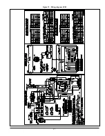
Please refer to Figures 2 to 8, the wiring diagrams, Figures
12 and 13, and the detailed instructions supplied with the
BVSO for the installation and wiring procedures. The length
of wires supplied with the unit is such that the safety device
must be installed between the flue outlet of the appliance
and the draft regulator, as indicated in the instructions.
Figure 2 : Wiring diagram,BVSO
For more details, refer to the instructions supplied with the
device itself, as well as section 3 of this manual.
DNS-01340 Rev A
Summary of Contents for CBMAAA060120
Page 21: ...21 Figure 13 Wiring diagram CVM ...
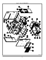
Page 22: ...22 Figure 14 Parts list CVMAAR036105 B50003 Rev D ...
Page 24: ...24 Figure 15 Parts list CVMAAR060120 B50004 Rev F ...
Page 48: ...23 Figure 13 Diagramme électrique CVM ...
Page 49: ...24 Figure 14 Liste de pièces CVMAAR036105 B50003 Rev D ...
Page 51: ...26 Figure 15 Liste de pièces CVMAAR060120 B50004 Rev F ...


