11
or left side panel, or on the bottom of the furnace to
accommodate the return air ductwork. A sufficient clearance
should be provided for air filter access. Please refer to Table
2 for filter rack flange dimensions for return air duct.
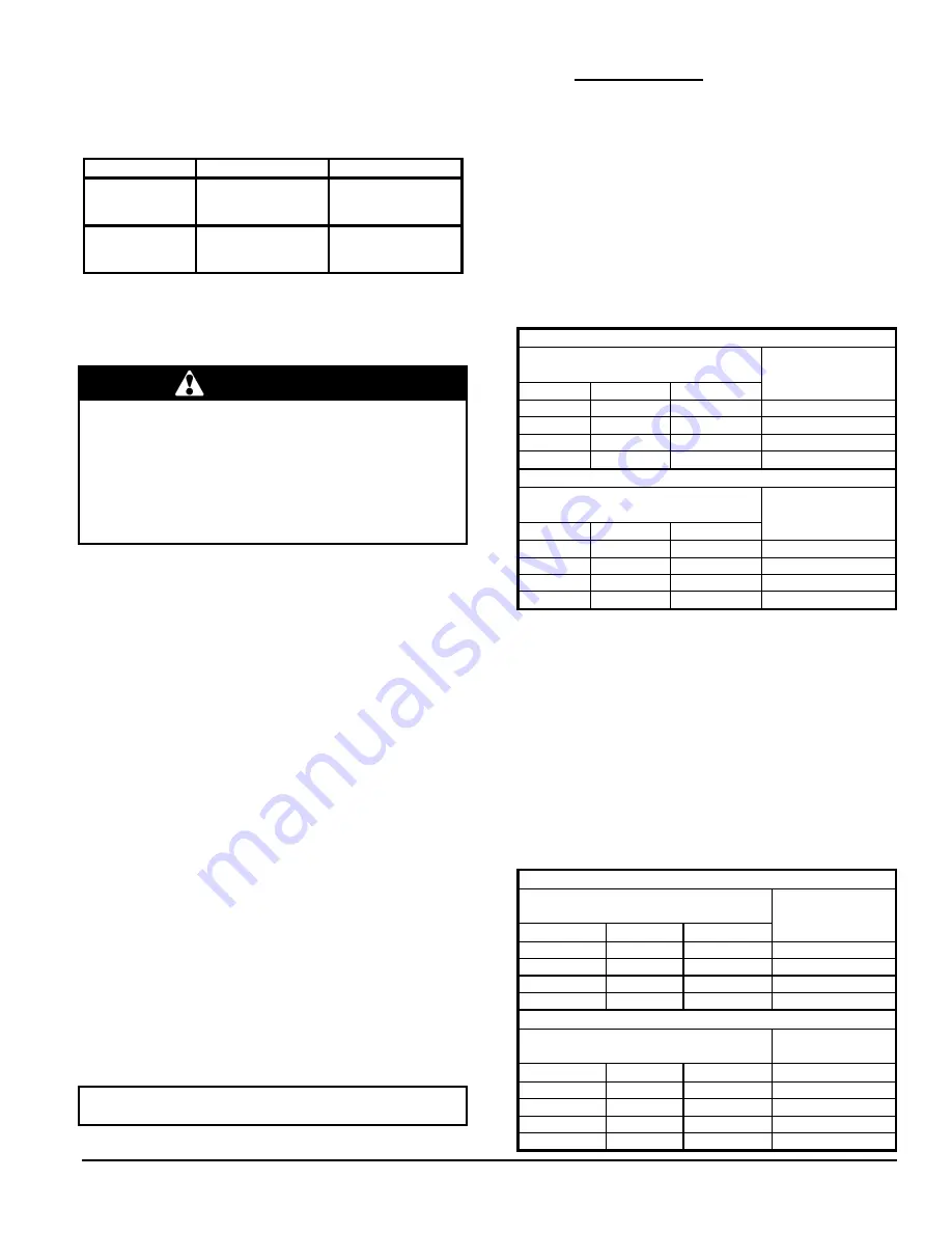
Table 2 : Filter rack flange dimensions for return air duct
Model
Air Filter Size
Flange Opening
16" x 24"
15" x 23"
CBM SIZE 105
40.64 x 60.96 cm
38.10 X 58.42 cm
20" x 30"
17" x 29"
CBM SIZE 120
45.72 X 76.20 cm
43.18 X 73.66 cm
2.4.9
Air Conditioner (or Heat Pump)
An air conditioning coil may be installed on the supply air
side ONLY.
WARNING
POISONOUS CARBON MONOXIDE GAS HAZARD
Install the evaporator coil on the supply side of the
furnace ducting ONLY.
An evaporator coil installed on the return air side of the
ducting can cause condensation to form inside the heat
exchanger, resulting in heat exchanger failure. This in
turn can result in death, bodily injury.
No minimum clearance is required between the bottom of
the coil drain pan and the top of the heat exchanger. If a
heat pump is installed, a “dual-energy” thermostat, or other
control is required, in order to prevent the simultaneous
operation of the furnace and the heat pump. It also prevents
a direct transition from heating by way of the heat pump to
heating with oil. Refer to the thermostat instructions or those
of another control used for the proper wiring.
If a coil blower compartment is used, install air tight,
motorized and automatic air dampers. Cold air coming from
the coil and passing across the furnace can cause
condensation and shorten the life of the heat exchanger.
2.4.10 Horizontal or downflow installation
1. On horizontal installations, determine which “side” will
become the “top”, when the unit is laid down. Remove
the flue pipe clearance knockout from the top front of
that side panel. Install the flue elbow so that it exits the
cabinet of the furnace through that opening;
2. On counterflow Installations, the flue pipe must exit the
cabinet through one of the side panel openings (as
above), then extended up the side of the furnace.
Ensure that adequate clearances to combustibles are
observed. It may be necessary to install a sheet-metal
shield on an adjacent wall to prevent any possibility of a
fire hazard;
3. Remove the burner by unscrewing the mounting nuts.
Avoid putting undue strain on burner wiring. It may be
necessary to disconnect the burner wiring in some
cases. Reinstall the burner in the proper position.
IMPORTANT: The burner must always be installed in the
upright position with the ignition control on top.
3.0 OPERATION
3.1
SUPPLY AIR ADJUSTMENTS
This furnace is equipped with an ECM variable speed motor.
The blower is adjusted at the factory to deliver the required
oil heating airflow at 0.75 USGPH and 3.0 tons of cooling on
models with a maximum input of 105,000 BTU/H. The same
applies to units with 0.85 USGPH input, 5 tons of cooling
and a maximum input of 154,000 BTUH.
Refer to Tables 3 to 6 for information on how to adjust the
DIP switches for other blower speeds for heating and
cooling.
Table 3 : Supply air adjustments, heating mode
CVM 105
SW1 – HEAT
DIP Switch Positions
1
2
POSITION
Output
USGPH
OFF
OFF
A
0.75
ON
OFF
B
0.65
OFF
ON
C
0.50
ON
ON
D
ALL
CVM 120
SW1 – HEAT
DIP Switch Positions
1
2
POSITION
Output
USGPH
OFF
OFF
A
0.85
ON
OFF
B
1.00
OFF
ON
C
1.10
ON
ON
D
N/A
3.2
OPERATIONAL CHECKLIST
Before starting up the unit, be sure to check that the
following items are in compliance:
1. The electrical installation, the oil supply system, the
venting system, combustion air supply and ventilation;
2. The blower access door is in place and the blower rail
locking screws are well tightened;
3. The Blocked Vent Shut-Off (BVSO) is installed
according to instructions (for chimney venting);
4. The oil supply valve is open;
Table 4 : Supply air adjustments, air conditioning mode
CVM 105
SW2 – COOL
DIP Switch Positions
1
2
POSITION
Output
Tons
OFF
OFF
A
3.0
ON
OFF
B
2.5
OFF
ON
C
2.0
ON
ON
D
1.5
CVM 120
SW2 – COOL
DIP Switch Positions
Output
Tons
1
2
POSITION
OFF
OFF
A
5.0
ON
OFF
B
4.0
OFF
ON
C
3.5
ON
ON
D
3.0
Summary of Contents for CBMAAA060120
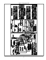
Page 21: ...21 Figure 13 Wiring diagram CVM ...
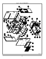
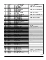
Page 22: ...22 Figure 14 Parts list CVMAAR036105 B50003 Rev D ...
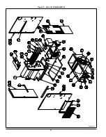
Page 24: ...24 Figure 15 Parts list CVMAAR060120 B50004 Rev F ...
Page 48: ...23 Figure 13 Diagramme électrique CVM ...
Page 49: ...24 Figure 14 Liste de pièces CVMAAR036105 B50003 Rev D ...
Page 51: ...26 Figure 15 Liste de pièces CVMAAR060120 B50004 Rev F ...


