INSTALLING THE TRMIM-10R
Page 3-5
Attaching STP Lobe Cables to the TRMIM-10R
1.
Connect the male DB-9 connector from one end of the STP lobe or
patch panel cable to the desired TCU port on the TRMIM-10R .
2.
If a patch panel is being used, connect the other end of the cable
to the appropriate patch panel jack. (Install DB-9 to MIC
adapters as needed.)
3.
Repeat this process for each station.
Attaching the STP Lobe Cable at the Station
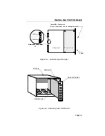
Cabling at the Token Ring station may require adapter patch cables
to permit mating between the wall plate and the station. Select the
appropriate patch cable: DB-9 at both ends, or DB-9 to Medium
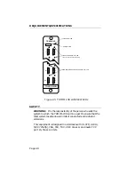
Interface Connector (MIC) (illustrated in Figure 3-4). If an adapter is
used, attach the adapter to the cable before connecting the twisted
pair cable to the station. Connect the wall plate end of the cable to
the wall plate. Connect the other end of the cable to the port on the
token ring station.
3.3.2 Connecting Trunk Cables
The TRMIM-10R Ring-In/Ring-Out ports support STP trunk cable
connections. Connect the STP trunk cables to the TRMIM-10R as
follows:
1.
Attach the male DB-9 connector at one end of the STP trunk cable
to its respective Ring-In or Ring-Out port.
NOTE: When only one TRMIM-10R is installed, forming an
independent ring network, wrap jumpers must be installed at the
Ring-In and Ring-Out ports of the TRMIM-10R.


