MAINTENANCE
OPERATOR MANUAL
70
EPS14P
71
OM-EPS14P2019001-EN
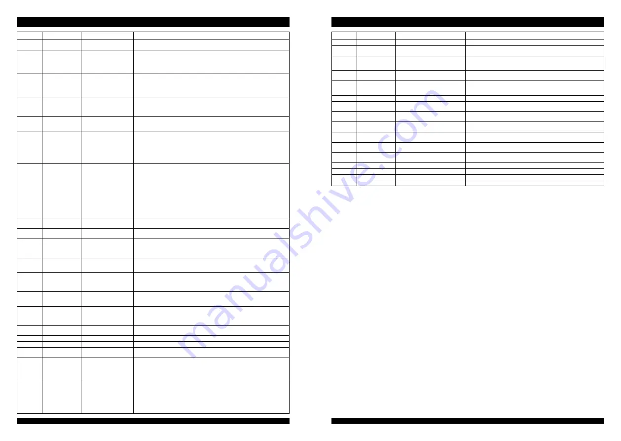
Display
ALARM
Fault name
Recommended inspection
06A19
KM OPEN
Main contactor of slave
contactor open
Slave contactor monitors the open of safety contactor of main contactor, and the
controller needs to be replaced;
06A20
MAIN CONT.OPEN
Main contactor open
The coil of main contactor has been energized by the logic card, but the contactor
does not engage. Possible cause:
1.The contactor has mechanically become faulty, or its contacts get stuck
2.The contacts of contactor cannot make securely
3.If the contactor operates normally, replace the controller.
06A21
MICRO SLAVE
The information on the
status bus between the
main microprocessor and
slave microprocessor is
frozen to the OXFF value.
The controller should be replaced;
06A22
S.P OUT OF RANGE Output steering poten-
tiometer out of range
If a single potentiometer, such as CPOC1 end, is out of range 0.8V-4.2V, it will
alarm. When the dual potentiometer is selected, the sum of the two sliding ends
(CPOC1+CPOC2) is out of the range of 4.4V-5.5V and it will alarm. Check the
connection of potentiometer.
06A23
F.B OUT OF RANGE Feedback of steering motor
encoder out of range
Feedback potentiometer (CPOT connecting to CNB#6) has fault, it will alarm. The
range of CPOT is out of 0.3V-4.7V, it will alarm. Check if the steering motor encoder is
connected correctly and whether there is a open circuit;
06A24
MICRO SLAVE KO
M a i n a n d s l a ve m i c ro -
processor detection does
not match
1.When using a stepper motor, the direction of the stepper motor detected by the
main microprocessor and slave microprocessor is inconsistent;
2.In the closed-loop control system, the direction of the stepper motor detected by the
main contactor is incorrect and is inconsistent with the direction of the stepper motor
detected by the slave contactor;
3.The main contactor did not detect the steering limit position, but it was detected by
the slave contactor;
06A25
ENCODER ERROR
Encoder fault
The controller detects that two successive speed readings of the encoder differs
greatly from each other. A normal encoder in the system cannot change speed
readings greatly within a very short time. Hence, a possible cause for the symptom is
that the wires of one or more encoders are worn or broken. Check the mechanical and
electrical parts of the encoder. Another possible for the symptom is electromagnetic
interference from the sensor bearing. If the symptom is not due to the two causes,
replace the controller.
Note: Sometimes manual operations may also cause this fault indicating on the
controller. In these cases, it is required to turn off power supply and start the forklift
again. For example:
1.The forklift suddenly collides with an obstacle so that it is incapable of travelling;
2.The driver applies the brake sharply while the forklift is travelling at a high speed
06A26
BAD ENCODER SIGN Encoder phase sequence
error
Change encoder A, B phase;
06A27
GAIN EEPROM KO
EEPROM memory current
value is different
Replace the controller;
06A28
CAN BUS KO
CAN BUS communica-tion
fault
1.Check if the CAN BUS communication line is connected properly;
2.Check if the bit rate of the communication is consistent;
3.Check if the CAN communication is open;
4.Check if the CAN communication loop resistance is 60Ω.
06A38
POSITION ERROR
Position error
1.Check if the steering motor encoder A and B phases are loosely connected;
2.Check if the steering motor A and B phases receive interference;
06A39
SERIAL ERROR #1
Slave contactor does not
receive the information of
main contactor from serial
port
Replace the controller;
06A40
MICRO SLAVE #4
Steering motor current is
opposite to the command
direction
Replace the controller;
06A41
SLAVE COM. ERROR
Main contactor does not
receive the information of
slave contactor from serial
port
Replace the controller;
06A43
CURRENT GAIN
Controller maximum current
is not controlled
Replace the controller;
06A44
CLOCK PAL NOT OK Clock error
Replace the controller;
06A45
STEER SENSOR KO
Dual potentiometer fault
Check the wiring and output of the two-way steering potentiometer.
06A46
JERKING FB
Steering potentiometer
voltage changes too much
Replace the feedback potentiometer;
06A47
FB POT LOCKED
Feedback value of steering
poten-tiometer locked
1.Check if the feedback steering potentiometer has mechanical looseness;
2.Check if there is a mechanical limit;
3.Check if the feedback steering potentiometer reaches its own limit point;
4.If the fault occurs in the opposite direction of the steering wheel during installation,
adjust the direction of the steering wheel;
06A48
MOTOR TEMPERAT. Motor temperature high
1.If the motor temperature digital switch is turned on, or analogue signal exceeds
the cutout value, then the fault results.2.When motor temperature rises to 120° C, the
controller will display the warning. The forklift still can travel but the maximum current
is reduced with the forklift performance degraded. When the motor temperature
reaches 125° C, the motor stops working. In this case, action shall be taken to cool the
motor.3.The fault still exists when the motor cools, check the line. If all have no faults,
replace the controller.
Display
ALARM
Fault name
Recommended inspection
06A49
MOTOR LOCKED
Steering motor stalling
Steering motor continuous maximum current time exceeds 1s;
06A50
STEPPER MOT MISM Frequency of stepper motor Q and D
line and voltage values do not match
Replace the controller;
06A52
MICRO SLAVE #8
The encoder of the main micropro-
cessor is inconsistent with the encoder
of the slave microprocessor
Replace the controller;
06A53
INPUT ERROR #1
Advanced steering controller CAN#4
has a voltage input higher than 12V
Check if the CAN#4 cable is correct;
06A54
CAN BUS KO SL.
Slave contactor does not receive any
CAN information from main con-
tactor
Replace the controller;
06A55
SL EPS NOT ALL.
Self centering is not completed
Replace the controller;
06A56
SL CENTERING
Swing angle of self centering is out of
range
Replace the controller;
16A06
Communication fault
Check the CAN cables of control handle, instrument panel, and steering
controller
17A01
battery high temp.
waring
Battery high temperature warning
17A02
battery high temp.
alarm
Battery high temperature alarm
17A03
b a t t e r y l e a k a g e
waring
Battery leakage warning
17A04
b a t t e r y l e a k a g e
serious
Battery leakage alarm
17A05
battery Status Alarm Battery status alarm
17A06
BDI low
Battery level low (SOC ≤ 10%)
17A07
BDI low
Cell voltage too low, general warn-ing
17A08
BDI low
Cell voltage too low, severe warning
Summary of Contents for EPS14P
Page 1: ...EPS14P OPERATOR MANUAL OM EPS14P2019001 EN...
Page 2: ...EPS14P OPERATOR MANUAL OM EPS14P2019001 EN...
Page 38: ......


